AIR SWITCHING VALVE(for Bank 1) INSTALLATION
PROCEDURE
-
INSTALL EMISSION CONTROL VALVE SET
-
Install the emission control valve set with the 3 nuts.
- Torque:
- 21 N*m { 214 kgf*cm, 15 ft.*lbf }
-

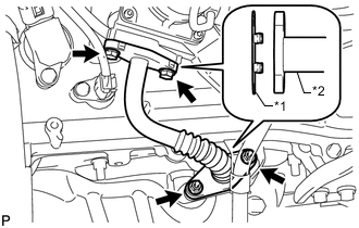
Text in Illustration *1 Rib *2 Paint mark *a RH Side *b Upper Align the paint mark with the projection and connect the No. 1 air hose.
Tech Tips
Make sure the direction of the hose clamp is as shown in the illustration.
-
Connect the emission control valve set connector.
-
-
INSTALL AIR TUBE
-
Text in Illustration *1 New Gasket *2 Air Tube Install 2 new gaskets to the air tube.
-
Install the air tube with the 2 bolts and 2 nuts.
- Torque:
- 10 N*m { 102 kgf*cm, 7 in.*lbf }
-
-
CONNECT WATER HOSE JOINT
-
Connect the water hose joint with the bolt.
- Torque:
- 5.4 N*m { 55 kgf*cm, 48 in.*lbf }
-
-
INSTALL AIR CLEANER CASE SUB-ASSEMBLY
-
Install the air cleaner case with the 3 bolts.
- Torque:
- 12 N*m { 122 kgf*cm, 9 ft.*lbf }
-
Attach the wire harness clamp.
-
Install the air cleaner filter element.
-
-
INSTALL AIR CLEANER CAP AND HOSE
-
INSTALL V-BANK COVER
-
INSTALL UPPER RADIATOR SUPPORT SEAL