FUEL TANK(for 5 Door) INSTALLATION
PROCEDURE
-
INSTALL FUEL TANK TO FILLER PIPE HOSE
-
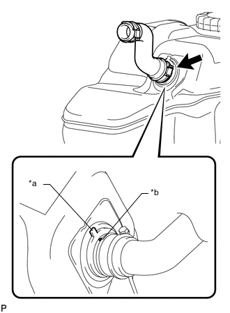
Text in Illustration *a Fuel Tank Sub-assembly Side Mark *b Hose Side Mark Align the fuel tank sub-assembly side mark with the hose side mark.
-
Install the fuel tank to filler pipe hose to the fuel tank sub-assembly.
-
-
INSTALL NO. 3 FUEL TANK PROTECTOR
-
Install the No. 3 fuel tank protector and attach the 4 clamps.
-
Install the 2 bolts.
- Torque:
- 5.0 N*m { 51 kgf*cm, 44 in.*lbf }
-
-
INSTALL FUEL SUCTION WITH PUMP AND GAUGE TUBE ASSEMBLY
-
INSTALL FUEL TANK MAIN TUBE SUB-ASSEMBLY AND FUEL RETURN TUBE SUB-ASSEMBLY (for Single Tank Type)
-
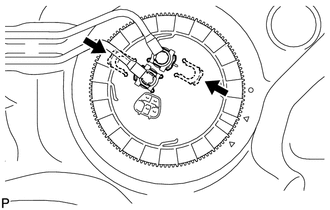
Install the fuel tank main tube sub-assembly and fuel return tube sub-assembly with the 2 fuel tube joint clips.
Note
-
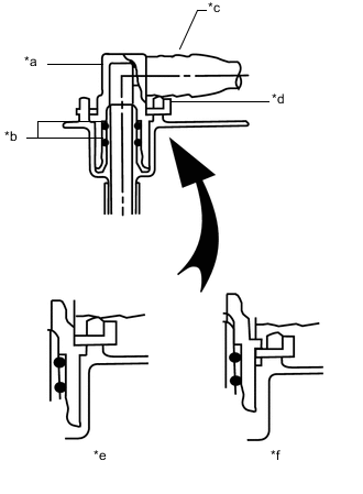
Check that there are no scratches or foreign objects on the connecting parts.
-
Check that the fuel tube joints are inserted securely.
-
Check that the fuel tube joint clips are on the collars of the fuel tube joints.
-
After installing the fuel tube joint clips, check that the fuel tube joints cannot be pulled off.
Text in Illustration *a Fuel Tube Joint *b O-Ring *c Fuel Tube *d Fuel Tube Joint Clip *e CORRECT *f INCORRECT
-
-
Install the fuel tank main tube sub-assembly and fuel return tube sub-assembly to the fuel tank sub-assembly.
-
-
INSTALL FUEL TANK MAIN TUBE SUB-ASSEMBLY, FUEL RETURN TUBE SUB-ASSEMBLY AND NO. 2 FUEL MAIN TUBE SUB-ASSEMBLY (for Double Tank Type)
-
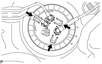
Install the fuel tank main tube sub-assembly, fuel return tube sub-assembly and No. 2 fuel main tube sub-assembly with the 3 fuel tube joint clips.
Note
-
Check that there are no scratches or foreign objects on the connecting parts.
-
Check that the fuel tube joints are inserted securely.
-
Check that the fuel tube joint clips are on the collars of the fuel tube joints.
-
After installing the fuel tube joint clips, check that the fuel tube joints cannot be pulled off.
Text in Illustration *a Fuel Tube Joint *b O-Ring *c Fuel Tube *d Fuel Tube Joint Clip *e CORRECT *f INCORRECT
-
-
Install the fuel tank main tube sub-assembly and fuel return tube sub-assembly to the fuel tank sub-assembly.
-
Install the No. 2 fuel main tube sub-assembly to the fuel tank sub-assembly and attach the clamp.
-
-
INSTALL FUEL TANK CUSHION
-
Install 3 new fuel tank cushions to the fuel tank sub-assembly.
-
-
INSTALL FUEL TANK SUB-ASSEMBLY
-
Set the fuel tank sub-assembly on an engine lifter and lift up the engine lifter.
Note
Do not allow the fuel tank sub-assembly to contact the vehicle, especially the differential.
-
Install the 2 fuel tank band sub-assemblies with the 2 pins and 2 clips.
-
Connect the 2 fuel tank band sub-assemblies with the 2 bolts.
- Torque:
- 40 N*m { 408 kgf*cm, 30 ft.*lbf }
-
-
CONNECT FUEL TANK TO FILLER PIPE HOSE
-
Connect the fuel tank to filler pipe hose to the filler pipe.
-
-
CONNECT FUEL CUT OFF TUBE (for Single Tank Type)
-
Connect the fuel cut off tube Click here.
-
-
CONNECT FUEL CUT OFF TUBE (for Double Tank Type)
-
Connect the fuel cut off tube Click here.
-
-
CONNECT FUEL TANK BREATHER TUBE SUB-ASSEMBLY (for Single Tank Type)
-
Connect the fuel tank breather tube sub-assembly Click here.
-
-
CONNECT FUEL TANK BREATHER TUBE SUB-ASSEMBLY (for Double Tank Type)
-
Connect the fuel tank breather tube sub-assembly Click here.
-
-
CONNECT NO. 2 FUEL MAIN TUBE SUB-ASSEMBLY (for Double Tank Type)
-
Connect the No. 2 fuel main tube sub-assembly Click here.
-
-
CONNECT FUEL RETURN TUBE SUB-ASSEMBLY
-
Connect the fuel return tube sub-assembly Click here.
-
-
CONNECT FUEL TANK MAIN TUBE SUB-ASSEMBLY
-
Connect the fuel tank main tube sub-assembly Click here.
-
-
INSTALL NO. 1 FUEL TANK PROTECTOR SUB-ASSEMBLY
-
Install the No. 1 fuel tank protector sub-assembly with the 6 bolts.
- Torque:
- 20 N*m { 204 kgf*cm, 15 ft.*lbf }
-
-
INSTALL REAR FLOOR SERVICE HOLE COVER
-
Connect the fuel pump and fuel sender gauge connector.
-
Install the rear floor service hole cover with the 3 screws.
-
-
INSTALL REAR SEAT ASSEMBLY LH
-
for 60/40 Split Double-folding Seat Type LH Side: Click here
-
for 60/40 Split Slide Walk-in Seat Type LH Side: Click here
-
-
CONNECT CABLE TO NEGATIVE BATTERY TERMINAL
Note
When disconnecting the cable, some systems need to be initialized after the cable is reconnected Click here.
-
INSPECT FOR FUEL LEAK