FUEL INJECTOR INSTALLATION

CAUTION / NOTICE / HINT
Tech Tips
Perform "Inspection After Repairs" after replacing the fuel injector Click here.
PROCEDURE
-
INSTALL FUEL INJECTOR ASSEMBLY
Tech Tips
Perform "Inspection After Repairs" after replacing the fuel injector Click here.
-
Apply a light coat of gasoline or spindle oil to new O-rings, then install one onto each fuel injector assembly.
-
Apply a light coat of gasoline or spindle oil to the contact surfaces of the fuel delivery pipe and the O-ring of the fuel injector assembly.
-
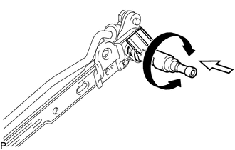
Apply a light coat of gasoline or spindle oil to the O-ring again, then install the fuel injector assembly into the fuel delivery pipe by turning it right and left.
Text in Illustration 
Turn 
Push Note
Make sure that the O-ring is not cracked or jammed when installing.
-
Check that the fuel injector assembly rotates smoothly.
If the fuel injector assembly does not rotate, replace the O-ring.
-
-
INSTALL FUEL DELIVERY PIPE WITH FUEL INJECTOR
-
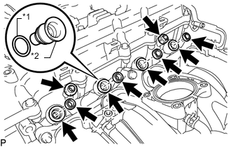
Text in Illustration *1 New O-Ring *2 Spacer Apply a light coat of gasoline or spindle oil to new O-rings, and then install one to each spacer.
-
Install the 4 spacers to the cylinder head sub-assembly.
-
Install 4 new injector vibration insulators to the cylinder head sub-assembly.
-
Install the 2 No. 1 delivery pipe spacers to the cylinder head sub-assembly.
-
Install the fuel delivery pipe together with the 4 fuel injector assemblies, and then temporarily install the fuel delivery pipe with the 2 bolts.
Note
Do not drop the fuel injector assemblies when installing the fuel delivery pipe.
-
Check that the fuel injector assemblies rotate smoothly.
If any fuel injector assembly does not rotate, replace its O-ring.
-
Tighten the 2 bolts.
- Torque:
- 12 N*m { 122 kgf*cm, 9 ft.*lbf }
-
Connect the purge VSV with the bolt.
- Torque:
- 9.0 N*m { 92 kgf*cm, 80 in.*lbf }
-
Connect the harness clamp bracket with the bolt.
- Torque:
- 8.0 N*m { 82 kgf*cm, 71 in.*lbf }
-
Attach the wire harness clamp.
-
Connect the purge VSV connector.
-
Connect the 4 fuel injector assembly connectors.
-
-
INSTALL FUEL PRESSURE PULSATION DAMPER ASSEMBLY
-
CONNECT FUEL HOSE
-
Connect the fuel hose Click here.
-
-
CONNECT NO. 2 FUEL HOSE
-
Connect the No. 2 fuel hose, and slide the clamp to secure the hose.
-
-
INSTALL THROTTLE BODY WITH MOTOR ASSEMBLY
-
CONNECT CABLE TO NEGATIVE BATTERY TERMINAL
Note
When disconnecting the cable, some systems need to be initialized after the cable is reconnected Click here.
-
INSPECT FOR FUEL LEAK
-
Make sure that there are no fuel leaks after performing maintenance on the fuel system.
-
Connect the GTS to the DLC3.
-
Turn the ignition switch to ON and turn the GTS on.
Note
Do not start the engine.
-
Enter the following menus: Powertrain / Engine and ECT / Active Test / Control the Fuel Pump / Speed.
-
Check that there are no leaks from the fuel system.
If there are fuel leaks, repair or replace parts as necessary.
-
Turn the ignition switch off.
-
Disconnect the GTS from the DLC3.
-
-