FUEL INJECTOR INSPECTION

PROCEDURE
-
INSPECT FUEL INJECTOR ASSEMBLY
-
Measure the resistance according to the value(s) in the table below.
Standard Resistance Tester Connection Condition Specified Condition 1 - 2 20°C (68°F) 11.6 to 12.4 Ω If the result is not as specified, replace the fuel injector assembly.
-
-
INSPECT INJECTION VOLUME AND LEAKAGE
-
Check the injection volume.
CAUTION:
This test involves high-pressure fuel and electricity, therefore, safety precautions should be taken. Perform this test in a safe area and avoid any sparks and flames. Do not smoke.
-
Discharge the fuel system pressure Click here.
-
Remove the fuel hose from the fuel pressure pulsation damper assembly Click here.
-
Remove the fuel hose from the fuel filter assembly Click here.
-
Disconnect the fuel pressure regulator Click here.
Note
Do not disconnect the No. 2 fuel hose.
-
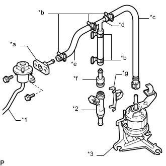
Text in Illustration *1 Fuel Pressure Regulator *2 Fuel Injector Assembly *3 Fuel Filter Assembly *a SST (Union) *b SST (Hose Band) *c SST (Fuel Tube Connector) *d SST (3 Way) *e SST (Hose) *f SST (Adapter) *g SST (Clamp) Assemble SST as shown in the illustration.
- SST
- 09268-31014 ( 09268-41091, 09268-41110, 09268-41120, 09268-41310, 09268-41500, 09268-41700, 95336-08070 )
-
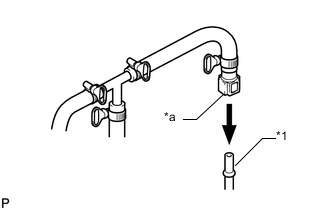
Text in Illustration *1 Fuel Filter Assembly *a SST (Fuel Tube Connector) Connect SST to the fuel filter assembly.
- SST
- 09268-31014 ( 09268-41500 )
-
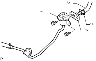
Text in Illustration *1 Fuel Pressure Regulator *a SST (Hose Band) *b SST (Union) *c SST (Hose) Install the fuel pressure regulator to SST (union) with the 2 bolts.
- SST
- 09268-31014 ( 09268-41091, 09268-41700, 95336-08070 )
- Torque:
- 9.0 N*m { 92 kgf*cm, 80 in.*lbf }
Note
Make sure that the O-ring is installed to the pressure regulator.
-
Install the O-ring to the fuel injector assembly.
-
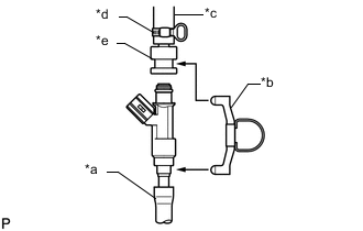
Text in Illustration *a Vinyl Tube *b SST (Clamp) *c SST (Hose) *d SST (Hose Band) *e SST (Adaptor) Assemble SST as shown in the illustration.
- SST
- 09268-31014 ( 09268-41110, 09268-41310, 09268-41700, 95336-08070 )
-
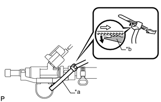
Text in Illustration *a SST (Tie Band) *b Lock Pass SST (tie band) through the loop on the handle of SST (clamp) to secure SST (clamp) to SST (adapter).
- SST
- 09268-31014 ( 09268-41800 )
Note
-
As SST (tie band) does not completely prevent SST (clamp) from becoming loose, do not subject the parts to any impacts while using them.
-
Before using SST (tie band), make sure that there is no deterioration, damage or cracks. If there are any abnormalities, replace SST.
Tech Tips
When removing SST (tie band), disengage the lock.
-
Check that SST (clamp) and SST (adapter) cannot be easily separated.
-
Put the fuel injector assembly into a graduated cylinder.
CAUTION:
Install a suitable vinyl tube to the fuel injector assembly to contain any gasoline spray.
-
Operate the fuel pump Click here.
-
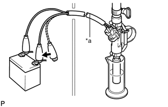
Text in Illustration *a SST (EFI inspection wire H) 
Connect Connect SST (EFI inspection wire H) to the fuel injector assembly and the battery for 15 seconds and measure the injection volume with a graduated cylinder. Test each injector 2 or 3 times.
- SST
- 09842-30080
Standard injection volume 82 to 99 cm3 (5.0 to 6.0 cu in.) per 15 seconds Difference between each injector 17 cm3 (1.0 cu in.) or less Note
-
Make sure that SST (EFI inspection wire H) is securely connected.
-
Always do the switching at the battery side.
If the injection volume is not as specified, replace the fuel injector assembly.
-
-
Check the leakage.
-
In the condition above, disconnect the tester probes of SST (EFI inspection wire H) from the battery and check the fuel leakage from the fuel injector assembly.
Fuel leakage 1 drop or less in 25 minutes
-
-