FUEL SENDER GAUGE ASSEMBLY(for Double Tank Type) INSPECTION
PROCEDURE
-
INSPECT FUEL SENDER GAUGE ASSEMBLY (for Fuel Main Tank)
-
Check the fuel sender gauge assembly output voltage.
-
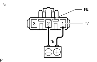
*a Component without harness connected
(Fuel Sender Gauge Assembly)
*b Voltage applied between terminals Apply 5 V between terminals 1 (FV) and 2 (FE).
Note
-
Be careful when connecting the leads, as the fuel sender gauge assembly may be damaged if the leads are connected to the wrong terminals.
-
Do not apply more than 6 V to terminals 1 (FV) and 2 (FE).
Tech Tips
If a stable power supply is not available, use 4 1.2 V nickel-metal hydride batteries or equivalent.
-
-
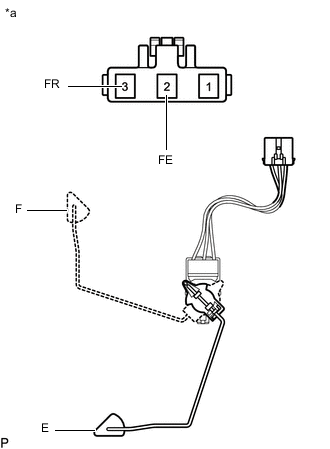
*a Component without harness connected
(Fuel Sender Gauge Assembly)
Measure the voltage according to the value(s) in the table below.
Standard Voltage Tester Connection Condition Specified Condition 2 (FE) - 3 (FR) Float position is F (upper) 4.255 to 4.605 V* Float position is E (lower) 0.345 to 0.695 V*
-
*: The output voltage changes depending on the voltage applied to the terminals.
Tech Tips
-
Output voltage(F) = (0.851 x Voltage applied to terminals) to (0.921 x Voltage applied to terminals)
-
Output voltage(E) = (0.069 x Voltage applied to terminals) to (0.139 x Voltage applied to terminals)
If the result is not as specified, replace the fuel sender gauge assembly.
-
-
-
-
INSPECT FUEL SENDER GAUGE ASSEMBLY (for Fuel Sub Tank)
-
Check the fuel sender gauge assembly output voltage.
-
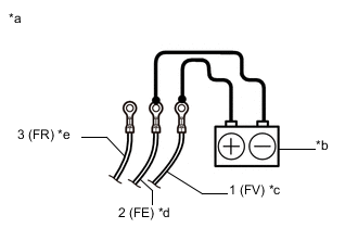
*a Component without harness connected
(Fuel Sender Gauge Assembly)
*b Voltage applied between terminals *c Lead Wire (Red) *d Lead Wire (Black) *e Lead Wire (Green) Apply 5 V between terminals 1 (FV) and 2 (FE).
Note
-
Be careful when connecting the leads, as the fuel sender gauge assembly may be damaged if the leads are connected to the wrong terminals.
-
Do not apply more than 6 V to terminals 1 (FV) and 2 (FE).
Tech Tips
If a stable power supply is not available, use 4 1.2 V nickel-metal hydride batteries or equivalent.
-
-
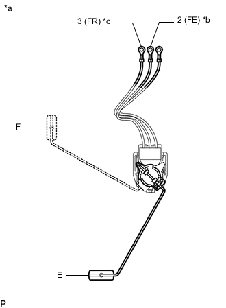
*a Component without harness connected
(Fuel Sender Gauge Assembly)
*b Lead Wire (Black) *c Lead Wire (Green) Measure the voltage according to the value(s) in the table below.
Standard Voltage Tester Connection Condition Specified Condition 2 (FE) - 3 (FR) Float position is F (upper) 4.255 to 4.605 V* Float position is E (lower) 0.345 to 0.695 V*
-
*: The output voltage changes depending on the voltage applied to the terminals.
Note
Be careful when connecting the leads, as the fuel sender gauge assembly may be damaged if the leads are connected to the wrong terminals.
Tech Tips
-
Output voltage(F) = (0.851 x Voltage applied to terminals) to (0.921 x Voltage applied to terminals)
-
Output voltage(E) = (0.069 x Voltage applied to terminals) to (0.139 x Voltage applied to terminals)
If the result is not as specified, replace the fuel sender gauge assembly.
-
-
-