FUEL TANK(for 5 Door) INSTALLATION

PROCEDURE
-
INSTALL FUEL TANK TO FILLER PIPE HOSE
-
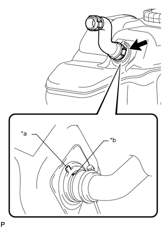
*a Fuel Tank Side Mark *b Hose Side Mark Align the fuel tank side mark with the hose side mark.
-
Install the fuel tank to filler pipe hose to the fuel tank sub-assembly, and tighten the clamp to secure the hose.
-
-
INSTALL NO. 3 FUEL TANK PROTECTOR
-
Install the No. 3 fuel tank protector and attach the 4 clamps.
-
Install the 2 bolts.
- Torque:
- 5.0 N*m { 51 kgf*cm, 44 in.*lbf }
-
-
INSTALL FUEL TANK VENT TUBE ASSEMBLY (for Single Tank Type)
-
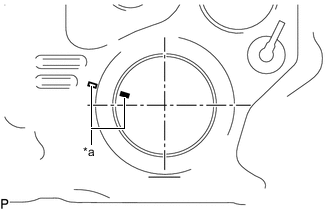
*a Co-rotation Prevention Check Mark Apply a co-rotation prevention check mark to the fuel tank vent tube assembly.
Tech Tips
Perform this procedure when replacement of the fuel tank vent tube assembly is necessary.
-
Apply a light coat of diesel fuel or grease to a new gasket and install the gasket to the fuel tank sub-assembly.
-
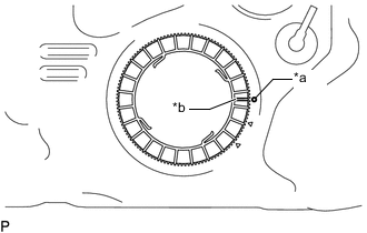
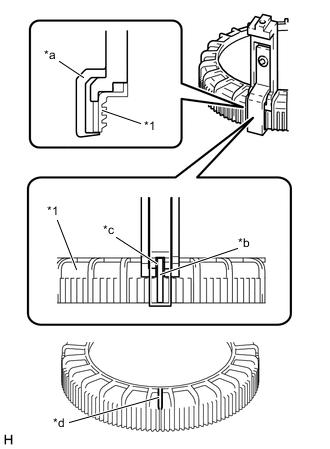
*a Protrusion *b Groove Set the fuel tank vent tube assembly to the fuel tank sub-assembly.
Note
Be careful not to bend the arm of the fuel sender gauge assembly.
Tech Tips
Align the cutout of the fuel tank vent tube assembly to the groove of the fuel tank sub-assembly.
-
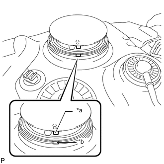
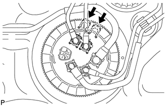
*a Rotational Start Point Mark (Fuel Tank Sub-assembly Side) *b Rotational Start Point Mark (Fuel Pump Gauge Retainer Side) Temporarily place the fuel pump gauge retainer by aligning the rotational start point mark of a new fuel pump gauge retainer with the rotational start point mark of the fuel tank sub-assembly while pressing the fuel tank vent tube assembly into the fuel tank sub-assembly.
-
*1 Fuel Pump Gauge Retainer *a SST (Claw Set) *b Rib *c Cutout *d SST (Claw Set) Incorrect Installation Point (Rotational Start Point Mark of Fuel Pump Gauge Retainer) Set 4 SSTs (claw sets) to the fuel pump gauge retainer and temporarily install.
- SST
- 09808-14031 ( 09808-01080, 09808-01090, 09808-01100 )
Note
-
Align the cutout of SST (claw set) to the rib of the fuel pump gauge retainer.
-
Do not place SST on the rotational start point mark of the fuel pump gauge retainer, otherwise SST (claw set) cannot be set correctly.
-
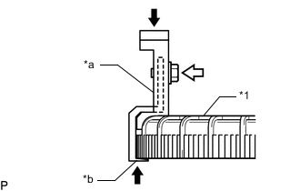
*1 Fuel Pump Gauge Retainer *a SST (Claw Set) *b Hook 
Press 
SST (Bolt) While firmly pressing the claw of SST (claw set) into rib of the fuel pump gauge retainer, tighten the bolt.
-
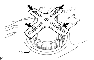
*a SST (Plate) *b SST (Claw Set) SST (Bolt) Temporarily install SST (plate) to SST (claw set) with 4 SSTs (bolts).
-
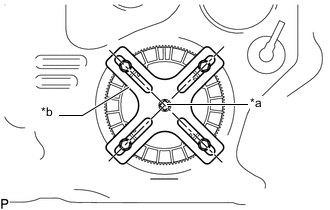
*a Center of Fuel Pump Gauge Retainer *b SST (Plate) Adjust the position of SST (plate) so that the setting hole of SST (handle) aligns with the center of the fuel pump gauge retainer.
-
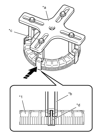
*1 Fuel Pump Gauge Retainer *a SST (Plate) *b SST (Claw Set) *c SST (Bolt) *d Rib 
Press While firmly pressing the SST (claw set) into rib of the fuel pump gauge retainer, tighten SST (bolt).
-
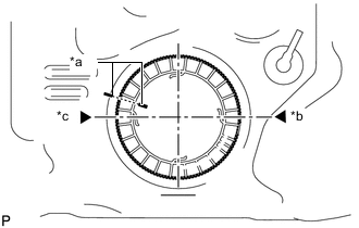
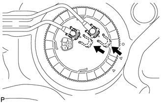
*a Co-rotation Prevention Check Mark *b Tightening Start Position *c One and Half Rotation Position While one person presses the fuel tank vent tube assembly into the fuel tank sub-assembly, have another person firmly press the fuel pump gauge retainer into the threads of the fuel tank sub-assembly and tighten approximately one and a half turns.
Note
-
Do not use any tools other than SST, such as a screwdriver, etc.
-
Do not use excessive force when pressing down on SST, as the fuel tank vent tube assembly will place excessive force on the pump gauge retainer and be difficult to remove, and parts may be damaged.
-
Do not use an impact wrench or turn the SST handle with excessive force, as parts may be damaged.
-
Do not rotate the fuel pump gauge retainer when the co-rotation prevention check mark is out of place.
-
-
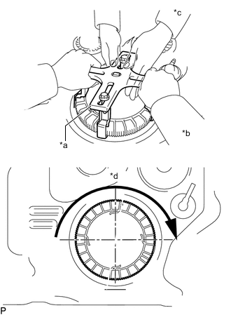
*a SST (Plate) *b Person in Charge of Tightening *c Person in Charge of Supporting *d Approximately 180° While one person presses the fuel tank vent tube assembly into the fuel tank sub-assembly, have another person slowly tighten approximately 180°.
-
Check the tightening condition of the fuel pump gauge retainer.
-
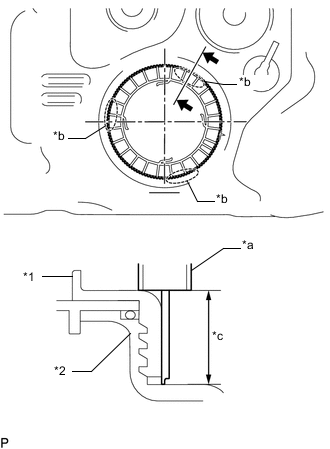
*1 Fuel Pump Gauge Retainer *2 Fuel Tank Sub-assembly *a Vernier Caliper *b Measurement Position *c Measurement Height Using a vernier caliper, measure the upper surface dimensions of the fuel tank sub-assembly at the 3 positions as shown in the illustration.
Standard Measurement difference is within 3 mm. Note
If the measurement difference is approximately 6 mm, the threads misaligned by 1 threads (6 mm) and the fuel pump gauge retainer must be installed again.
-
-
Install SST (handle) to SST (plate).
- SST
- 09808-14031 ( 09808-01010, 09808-01020 )
-
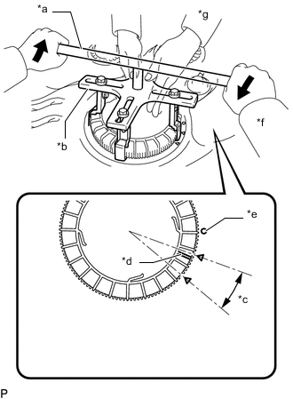
*a SST (Handle) *b SST (Plate) *c Tightening Complete Position *d Rotational Start Point Mark of Fuel Pump Gauge Retainer *e Rotational Start Point Mark of Fuel Tank Sub-assembly *f Person in Charge of Tightening *g Person in Charge of Supporting Tighten While one person presses the fuel tank vent tube assembly onto the fuel tank sub-assembly, have another person use SST (handle) and slowly tighten the fuel pump gauge retainer until it reaches the tightening complete position.
-
-
INSTALL FUEL SUCTION WITH PUMP AND GAUGE TUBE ASSEMBLY (for Double Tank Type)
-
INSTALL FUEL RETURN TUBE SUB-ASSEMBLY AND FUEL TANK MAIN TUBE SUB-ASSEMBLY (for Single Tank Type)
-
Install the fuel return tube sub-assembly and fuel tank main tube sub-assembly with the 2 fuel tube joint clips.
Note
-
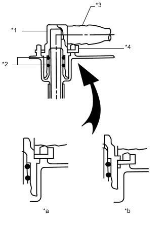
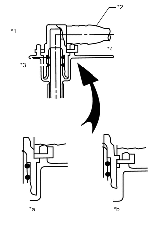
*1 Fuel Tube Joint *2 O-Ring *3 Fuel Tube *4 Fuel Tube Joint Clip *a CORRECT *b INCORRECT Check that there are no scratches or foreign objects on the connecting parts.
-
Check that the fuel tube joints are inserted securely.
-
Check that the fuel tube joint clips are on the collars of the fuel tube joints.
-
After installing the fuel tube joint clips, check that the fuel tube joints cannot be pulled off.
-
-
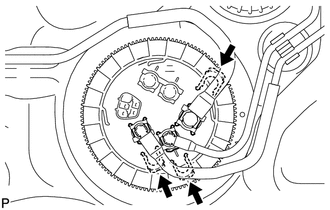
Install the fuel return tube sub-assembly and fuel tank main tube sub-assembly to the fuel tank sub-assembly.
-
-
INSTALL FUEL TANK MAIN TUBE SUB-ASSEMBLY, FUEL RETURN TUBE SUB-ASSEMBLY AND NO. 2 FUEL MAIN TUBE SUB-ASSEMBLY (for Double Tank Type)
-
Install the fuel tank main tube sub-assembly, fuel return tube sub-assembly and No. 2 fuel main tube sub-assembly with the 3 fuel tube joint clips.
Note
-
*1 Fuel Tube Joint *2 O-Ring *3 Fuel Tube *4 Fuel Tube Joint Clip *a CORRECT *b INCORRECT Check that there are no scratches or foreign objects on the connecting parts.
-
Check that the fuel tube joints are inserted securely.
-
Check that the fuel tube joint clips are on the collars of the fuel tube joints.
-
After installing the fuel tube joint clips, check that the fuel tube joints cannot be pulled off.
-
-
Install the fuel tank main tube sub-assembly to the fuel tank sub-assembly.
-
Install the fuel return tube sub-assembly to the fuel tank sub-assembly and attach the clamp.
-
Install the No. 2 fuel main tube sub-assembly to the fuel tank sub-assembly and attach the clamp.
-
-
INSTALL NO. 4 FUEL MAIN TUBE SUB-ASSEMBLY AND FUEL SUCTION TUBE SUB-ASSEMBLY (for Double Tank Type)
-
Install the No. 4 fuel main tube sub-assembly and fuel suction tube sub-assembly with the 2 fuel tube joint clips.
Note
-
*1 Fuel Tube Joint *2 O-Ring *3 Fuel Tube *4 Fuel Tube Joint Clip *a CORRECT *b INCORRECT Check that there are no scratches or foreign objects on the connecting parts.
-
Check that the fuel tube joints are inserted securely.
-
Check that the fuel tube joint clips are on the collars of the fuel tube joints.
-
After installing the fuel tube joint clips, check that the fuel tube joints cannot be pulled off.
-
-
Install the fuel suction tube sub-assembly to the fuel tank sub-assembly and attach the clamp.
-
Install the No. 4 fuel main tube sub-assembly to the fuel tank sub-assembly and attach the clamp.
-
-
INSTALL FUEL TANK CUSHION
-
Install 3 new fuel tank cushions to the fuel tank sub-assembly.
-
-
INSTALL FUEL TANK SUB-ASSEMBLY
-
Set the fuel tank sub-assembly on a transmission jack and lift up the transmission jack.
Note
Do not allow the fuel tank sub-assembly to contact the vehicle, especially the differential.
-
Install the 2 fuel tank bands with the 2 pins and 2 clips.
-
Connect the 2 fuel tank bands with the 2 bolts.
- Torque:
- 40 N*m { 408 kgf*cm, 30 ft.*lbf }
-
-
CONNECT FUEL TANK TO FILLER PIPE HOSE
-
Connect the fuel tank to filler pipe hose to the filler pipe, and tighten the clamp to secure the hose.
-
-
CONNECT FUEL TANK BREATHER TUBE SUB-ASSEMBLY (for Single Tank Type)
-
Connect the fuel tank breather tube sub-assembly Click here.
-
-
CONNECT FUEL CUT OFF TUBE (for Single Tank Type)
-
Connect the fuel cut off tube Click here.
-
-
CONNECT FUEL TANK BREATHER TUBE SUB-ASSEMBLY (for Double Tank Type)
-
Connect the fuel tank breather tube sub-assembly Click here.
-
-
CONNECT FUEL RETURN TUBE SUB-ASSEMBLY AND NO. 2 FUEL MAIN TUBE SUB-ASSEMBLY (for Double Tank Type)
-
Connect the fuel return tube sub-assembly and No. 2 fuel main tube sub-assembly Click here.
-
-
CONNECT FUEL CUT OFF TUBE (for Double Tank Type)
-
Connect the fuel cut off tube Click here.
-
-
CONNECT NO. 4 FUEL MAIN TUBE SUB-ASSEMBLY AND FUEL SUCTION TUBE SUB-ASSEMBLY (for Double Tank Type)
-
Connect the No. 4 fuel main tube sub-assembly and fuel suction tube sub-assembly Click here.
-
-
CONNECT FUEL RETURN TUBE SUB-ASSEMBLY (for Single Tank Type)
-
Connect the fuel return tube sub-assembly Click here.
-
-
CONNECT FUEL TANK MAIN TUBE SUB-ASSEMBLY (for Single Tank Type)
-
Connect the fuel tank main tube sub-assembly Click here.
-
-
CONNECT FUEL TANK MAIN TUBE SUB-ASSEMBLY (for Double Tank Type)
-
Connect the fuel tank main tube sub-assembly Click here.
-
-
INSTALL NO. 1 FUEL TANK PROTECTOR SUB-ASSEMBLY
-
for Type A:
-
Install the No. 1 fuel tank protector sub-assembly with the 6 bolts.
- Torque:
- 20 N*m { 204 kgf*cm, 15 ft.*lbf }
-
-
for Type B:
-
Install the No. 1 fuel tank protector sub-assembly with the 4 bolts.
- Torque:
- 20 N*m { 204 kgf*cm, 15 ft.*lbf }
-
-
-
INSTALL REAR FLOOR SERVICE HOLE COVER
-
Connect the fuel pump and fuel sender gauge connector.
-
Install the rear floor service hole cover with the 3 screws.
-
-
INSTALL REAR SEAT ASSEMBLY LH
-
for 60/40 Split Double-folding Seat Type LH Side:
-
for 60/40 Split Slide Walk-in Seat Type LH Side:
-
-
CONNECT CABLE TO NEGATIVE BATTERY TERMINAL
Note
When disconnecting the cable, some systems need to be initialized after the cable is reconnected Click here.
-
BLEED AIR FROM FUEL SYSTEM
-
INSPECT FOR FUEL LEAK