FUEL TANK(for 5 Door) INSTALLATION

PROCEDURE
-
INSTALL FUEL TANK TO FILLER PIPE HOSE
-
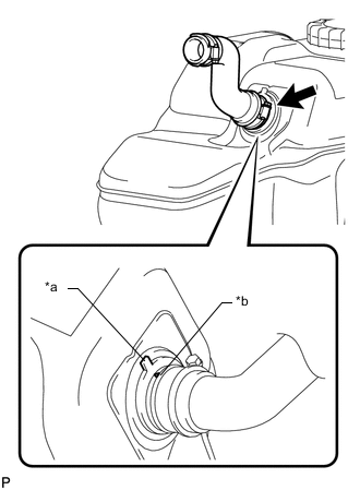
Text in Illustration *a Fuel Tank Side Mark *b Hose Side Mark Align the fuel tank side mark with the hose side mark.
-
Install the fuel tank to filler pipe hose to the fuel tank sub-assembly, and tighten the clamp to secure the hose.
-
-
INSTALL NO. 3 FUEL TANK PROTECTOR
-
Install the No. 3 fuel tank protector and attach the 4 clamps.
-
Install the 2 bolts.
- Torque:
- 5.0 N*m { 51 kgf*cm, 44 in.*lbf }
-
-
INSTALL FUEL TANK VENT TUBE ASSEMBLY (for Single Tank Type)
-
Apply a light coat of diesel fuel or grease to a new gasket and install the gasket to the fuel tank sub-assembly.
-
Text in Illustration *a Protrusion *b Groove Align the protrusion of the fuel tank vent tube assembly with the groove of the fuel tank sub-assembly.
Note
Be careful not to bend the arm of the fuel sender gauge assembly.
-
Install the fuel tank vent tube assembly to the fuel tank sub-assembly.
-
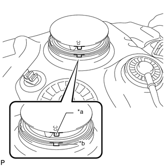
Put a new retainer on the fuel tank sub-assembly. While holding the fuel tank vent tube assembly, tighten the retainer one complete turn by hand.
Tech Tips
Make sure the start marks on the retainer and fuel tank sub-assembly are aligned and then tighten the retainer.
-
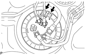
Text in Illustration *a Start Mark (Fuel Tank Side) *b Start Mark (Retainer Side) Set SST on the retainer.
- SST
- 09808-14030
Tech Tips
-
Hold the fuel tank vent tube assembly upright by hand to ensure that the gasket is not moved out of position.
-
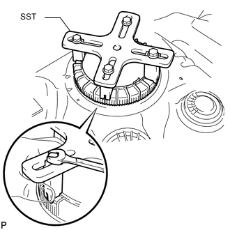
Engage the claws of SST securely with the retainer holes to secure SST.
-
Install SST while pressing the claws of SST against the retainer (toward the center of SST).
-
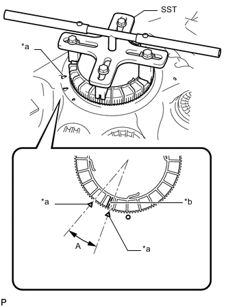
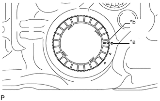
Text in Illustration *a Fuel Tank Side Mark *b Retainer Side Mark Using SST, tighten the retainer until the mark on the retainer is within range A on the fuel tank as shown in the illustration.
- SST
- 09808-14030
Tech Tips
Fit the tips of SST onto the ribs of the retainer.
-
-
INSTALL FUEL SUCTION WITH PUMP AND GAUGE TUBE ASSEMBLY (for Double Tank Type)
-
INSTALL FUEL RETURN TUBE SUB-ASSEMBLY AND FUEL TANK MAIN TUBE SUB-ASSEMBLY (for Single Tank Type)
-
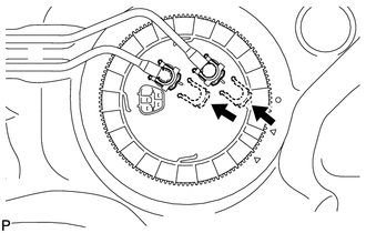
Install the fuel return tube sub-assembly and fuel tank main tube sub-assembly with the 2 fuel tube joint clips.
Note
-
Check that there are no scratches or foreign objects on the connecting parts.
-
Check that the fuel tube joints are inserted securely.
-
Check that the fuel tube joint clips are on the collars of the fuel tube joints.
-
After installing the fuel tube joint clips, check that the fuel tube joints cannot be pulled off.
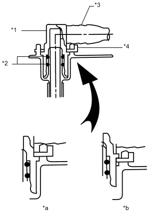
Text in Illustration *1 Fuel Tube Joint *2 O-Ring *3 Fuel Tube *4 Fuel Tube Joint Clip *a CORRECT *b INCORRECT
-
-
Install the fuel return tube sub-assembly and fuel tank main tube sub-assembly to the fuel tank sub-assembly.
-
-
INSTALL FUEL TANK MAIN TUBE SUB-ASSEMBLY, FUEL RETURN TUBE SUB-ASSEMBLY AND NO. 2 FUEL MAIN TUBE SUB-ASSEMBLY (for Double Tank Type)
-
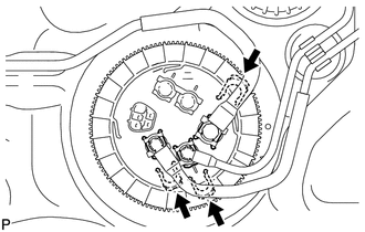
Install the fuel tank main tube sub-assembly, fuel return tube sub-assembly and No. 2 fuel main tube sub-assembly with the 3 fuel tube joint clips.
Note
-
Check that there are no scratches or foreign objects on the connecting parts.
-
Check that the fuel tube joints are inserted securely.
-
Check that the fuel tube joint clips are on the collars of the fuel tube joints.
-
After installing the fuel tube joint clips, check that the fuel tube joints cannot be pulled off.
Text in Illustration *1 Fuel Tube Joint *2 O-Ring *3 Fuel Tube *4 Fuel Tube Joint Clip *a CORRECT *b INCORRECT
-
-
Install the fuel tank main tube sub-assembly to the fuel tank sub-assembly.
-
Install the fuel return tube sub-assembly to the fuel tank sub-assembly and attach the clamp.
-
Install the No. 2 fuel main tube sub-assembly to the fuel tank sub-assembly and attach the clamp.
-
-
INSTALL NO. 4 FUEL MAIN TUBE SUB-ASSEMBLY AND FUEL SUCTION TUBE SUB-ASSEMBLY (for Double Tank Type)
-
Install the No. 4 fuel main tube sub-assembly and fuel suction tube sub-assembly with the 2 fuel tube joint clips.
Note
-
Check that there are no scratches or foreign objects on the connecting parts.
-
Check that the fuel tube joints are inserted securely.
-
Check that the fuel tube joint clips are on the collars of the fuel tube joints.
-
After installing the fuel tube joint clips, check that the fuel tube joints cannot be pulled off.
Text in Illustration *1 Fuel Tube Joint *2 O-Ring *3 Fuel Tube *4 Fuel Tube Joint Clip *a CORRECT *b INCORRECT
-
-
Install the fuel suction tube sub-assembly to the fuel tank sub-assembly and attach the clamp.
-
Install the No. 4 fuel main tube sub-assembly to the fuel tank sub-assembly and attach the clamp.
-
-
INSTALL FUEL TANK CUSHION
-
Install 3 new fuel tank cushions to the fuel tank sub-assembly.
-
-
INSTALL FUEL TANK SUB-ASSEMBLY
-
Set the fuel tank sub-assembly on a transmission jack and lift up the transmission jack.
Note
Do not allow the fuel tank sub-assembly to contact the vehicle, especially the differential.
-
Install the 2 fuel tank bands with the 2 pins and 2 clips.
-
Connect the 2 fuel tank bands with the 2 bolts.
- Torque:
- 40 N*m { 408 kgf*cm, 30 ft.*lbf }
-
-
CONNECT FUEL TANK TO FILLER PIPE HOSE
-
Connect the fuel tank to filler pipe hose to the filler pipe, and tighten the clamp to secure the hose.
-
-
CONNECT FUEL TANK BREATHER TUBE SUB-ASSEMBLY (for Single Tank Type)
-
Connect the fuel tank breather tube sub-assembly Click here.
-
-
CONNECT FUEL CUT OFF TUBE (for Single Tank Type)
-
Connect the fuel cut off tube Click here.
-
-
CONNECT FUEL TANK BREATHER TUBE SUB-ASSEMBLY (for Double Tank Type)
-
Connect the fuel tank breather tube sub-assembly Click here.
-
-
CONNECT FUEL RETURN TUBE SUB-ASSEMBLY AND NO. 2 FUEL MAIN TUBE SUB-ASSEMBLY (for Double Tank Type)
-
Connect the fuel return tube sub-assembly and No. 2 fuel main tube sub-assembly Click here.
-
-
CONNECT FUEL CUT OFF TUBE (for Double Tank Type)
-
Connect the fuel cut off tube Click here.
-
-
CONNECT NO. 4 FUEL MAIN TUBE SUB-ASSEMBLY AND FUEL SUCTION TUBE SUB-ASSEMBLY (for Double Tank Type)
-
Connect the No. 4 fuel main tube sub-assembly and fuel suction tube sub-assembly Click here.
-
-
CONNECT FUEL RETURN TUBE SUB-ASSEMBLY (for Single Tank Type)
-
Connect the fuel return tube sub-assembly Click here.
-
-
CONNECT FUEL TANK MAIN TUBE SUB-ASSEMBLY (for Single Tank Type)
-
Connect the fuel tank main tube sub-assembly Click here.
-
-
CONNECT FUEL TANK MAIN TUBE SUB-ASSEMBLY (for Double Tank Type)
-
Connect the fuel tank main tube sub-assembly Click here.
-
-
INSTALL NO. 1 FUEL TANK PROTECTOR SUB-ASSEMBLY
-
for Type A:
-
Install the No. 1 fuel tank protector sub-assembly with the 6 bolts.
- Torque:
- 20 N*m { 204 kgf*cm, 15 ft.*lbf }
-
-
for Type B:
-
Install the No. 1 fuel tank protector sub-assembly with the 4 bolts.
- Torque:
- 20 N*m { 204 kgf*cm, 15 ft.*lbf }
-
-
-
INSTALL REAR FLOOR SERVICE HOLE COVER
-
Connect the fuel pump and fuel sender gauge connector.
-
Install the rear floor service hole cover with the 3 screws.
-
-
INSTALL REAR SEAT ASSEMBLY LH
-
for 60/40 Split Double-folding Seat Type LH Side:
-
for 60/40 Split Slide Walk-in Seat Type LH Side:
-
-
CONNECT CABLE TO NEGATIVE BATTERY TERMINAL
Note
When disconnecting the cable, some systems need to be initialized after the cable is reconnected Click here.
-
BLEED AIR FROM FUEL SYSTEM
-
INSPECT FOR FUEL LEAK