FUEL TANK(for 5 Door) REMOVAL

PROCEDURE
-
DISCONNECT CABLE FROM NEGATIVE BATTERY TERMINAL
Note
-
After turning the ignition switch off, waiting time may be required before disconnecting the cable from the battery terminal. Therefore, make sure to read the disconnecting the cable from the battery terminal notice before proceeding with work Click here.
-
When disconnecting the cable, some systems need to be initialized after the cable is reconnected Click here.
-
-
REMOVE REAR SEAT ASSEMBLY LH
-
for 60/40 Split Double-folding Seat Type LH Side:
-
for 60/40 Split Slide Walk-in Seat Type LH Side:
-
-
REMOVE REAR FLOOR SERVICE HOLE COVER
-
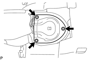
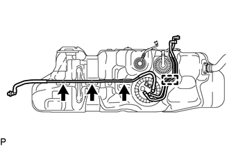
Remove the 3 screws and rear floor service hole cover.
-
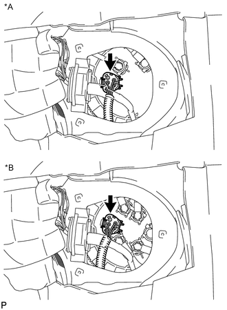
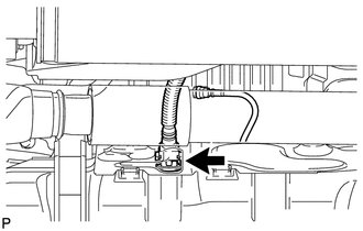
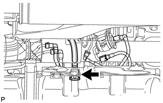
*A for Single Tank Type *B for Double Tank Type Disconnect the fuel pump and sender gauge connector.
-
-
REMOVE NO. 1 FUEL TANK PROTECTOR SUB-ASSEMBLY
-
for Type A:
-
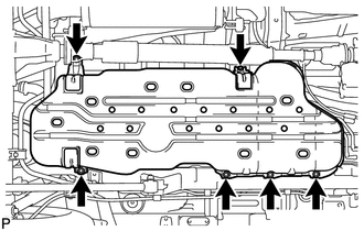
Remove the 6 bolts and No. 1 fuel tank protector sub-assembly.
-
-
for Type B:
-
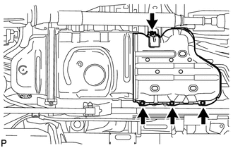
Remove the 4 bolts and No. 1 fuel tank protector sub-assembly.
-
-
-
DISCONNECT FUEL TANK MAIN TUBE SUB-ASSEMBLY (for Single Tank Type)
-
Disconnect the fuel tank main tube sub-assembly Click here.
-
-
DISCONNECT FUEL RETURN TUBE SUB-ASSEMBLY (for Single Tank Type)
-
Disconnect the fuel return tube sub-assembly Click here.
-
-
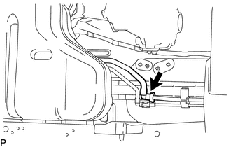
DISCONNECT FUEL TANK MAIN TUBE SUB-ASSEMBLY (for Double Tank Type)
-
Disconnect fuel tank main tube sub-assembly Click here.
-
-
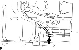
DISCONNECT FUEL CUT OFF TUBE (for Single Tank Type)
-
Disconnect the fuel cut off tube Click here.
-
-
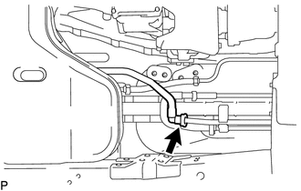
DISCONNECT FUEL TANK BREATHER TUBE SUB-ASSEMBLY (for Single Tank Type)
-
Disconnect the fuel tank breather tube sub-assembly Click here.
-
-
DISCONNECT NO. 4 FUEL MAIN TUBE SUB-ASSEMBLY AND FUEL SUCTION TUBE SUB-ASSEMBLY (for Double Tank Type)
-
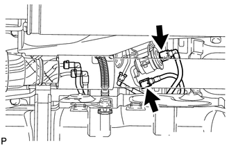
Disconnect the No. 4 fuel main tube sub-assembly and fuel suction tube sub-assembly Click here.
-
-
DISCONNECT FUEL CUT OFF TUBE (for Double Tank Type)
-
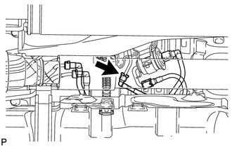
Disconnect the fuel cut off tube Click here.
-
-
DISCONNECT FUEL RETURN TUBE SUB-ASSEMBLY AND NO. 2 FUEL MAIN TUBE SUB-ASSEMBLY (for Double Tank Type)
-
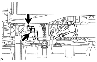
Disconnect the fuel return tube sub-assembly and No. 2 fuel main tube sub-assembly Click here.
-
-
DISCONNECT FUEL TANK BREATHER TUBE SUB-ASSEMBLY (for Double Tank Type)
-
Disconnect the fuel tank breather tube sub-assembly Click here.
-
-
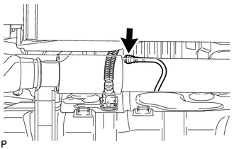
DISCONNECT FUEL TANK TO FILLER PIPE HOSE
-
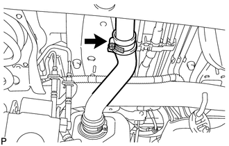
Loosen the clamp and disconnect the fuel tank to filler pipe hose from the filler pipe.
-
-
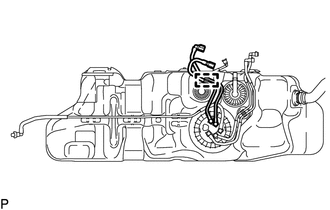
REMOVE FUEL TANK SUB-ASSEMBLY
-
Place a transmission jack under the fuel tank sub-assembly.
-
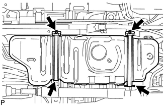
Remove the 2 bolts, 2 clips, 2 pins and 2 fuel tank bands.
-
Slowly lower the transmission jack slightly.
-
-
REMOVE FUEL TANK CUSHION
-
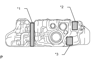
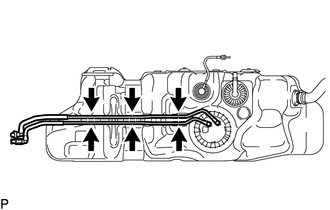
*1 No. 1 Fuel Tank Cushion *2 No. 2 Fuel Tank Cushion *3 No. 3 Fuel Tank Cushion Remove the No. 1, No. 2 and No. 3 fuel tank cushions from the fuel tank sub-assembly.
-
-
REMOVE FUEL RETURN TUBE SUB-ASSEMBLY AND FUEL TANK MAIN TUBE SUB-ASSEMBLY (for Single Tank Type)
-
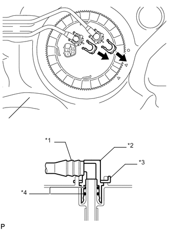
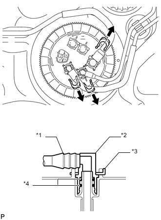
*1 Fuel Tube *2 Fuel Tube Joint *3 Fuel Tube Joint Clip *4 O-Ring Remove the 2 fuel tube joint clips and pull out the fuel return tube sub-assembly and fuel tank main tube sub-assembly.
Note
-
Remove any dirt and foreign matter on the fuel tube joint before performing this work.
-
Do not allow any scratches or foreign matter on the parts when disconnecting them, as the fuel tube joint contains the O-rings that seal the plug.
-
Perform this work by hand. Do not use any tools.
-
Do not forcibly bend, twist or turn the nylon tube.
-
Protect the disconnected part by covering it with a plastic bag and tape after disconnecting the fuel tubes.
-
-
Remove the fuel return tube sub-assembly and fuel tank main tube sub-assembly from the fuel tank sub-assembly.
-
-
REMOVE NO. 4 FUEL MAIN TUBE SUB-ASSEMBLY AND FUEL SUCTION TUBE SUB-ASSEMBLY (for Double Tank Type)
-
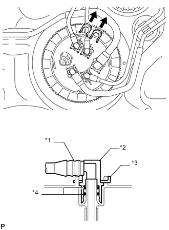
*1 Fuel Tube *2 Fuel Tube Joint *3 Fuel Tube Joint Clip *4 O-Ring Remove the 2 fuel tube joint clips and pull out the No. 4 fuel main tube sub-assembly and fuel suction tube sub-assembly.
Note
-
Remove any dirt and foreign matter on the fuel tube joint before performing this work.
-
Do not allow any scratches or foreign matter on the parts when disconnecting them, as the fuel tube joint contains the O-rings that seal the plug.
-
Perform this work by hand. Do not use any tools.
-
Do not forcibly bend, twist or turn the nylon tube.
-
Protect the disconnected part by covering it with a plastic bag and tape after disconnecting the fuel tubes.
-
-
Detach the clamp and remove the No. 4 fuel main tube from the fuel tank sub-assembly.
-
Detach the clamp and remove the fuel suction tube sub-assembly from the fuel tank sub-assembly.
-
-
REMOVE FUEL TANK MAIN TUBE SUB-ASSEMBLY, FUEL RETURN TUBE SUB-ASSEMBLY AND NO. 2 FUEL MAIN TUBE SUB-ASSEMBLY (for Double Tank Type)
-
*1 Fuel Tube *2 Fuel Tube Joint *3 Fuel Tube Joint Clip *4 O-Ring Remove the 3 fuel tube joint clips and pull out the fuel tank main tube sub-assembly, fuel return tube sub-assembly and No. 2 fuel main tube sub-assembly.
Note
-
Remove any dirt and foreign matter on the fuel tube joint before performing this work.
-
Do not allow any scratches or foreign matter on the parts when disconnecting them, as the fuel tube joint contains the O-rings that seal the plug.
-
Perform this work by hand. Do not use any tools.
-
Do not forcibly bend, twist or turn the nylon tube.
-
Protect the disconnected part by covering it with a plastic bag and tape after disconnecting the fuel tubes.
-
-
Detach the clamp and remove the No. 2 fuel main tube sub-assembly from the fuel tank sub-assembly.
-
Detach the clamp and remove the fuel return tube sub-assembly from the fuel tank sub-assembly.
-
Remove the fuel tank main tube sub-assembly from the fuel tank sub-assembly.
-
-
REMOVE FUEL TANK VENT TUBE ASSEMBLY (for Single Tank Type)
Note
Protect the connector and tube joint of the fuel tank vent tube assembly with vinyl tape to prevent foreign matter from entering. Then clean off any mud or other foreign matter before proceeding with work.
-
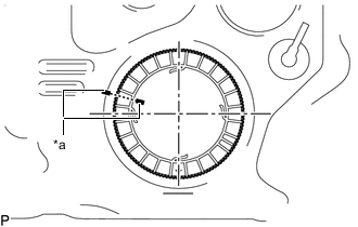
*a Co-rotation Prevention Check Mark Apply a co-rotation prevention check mark to the fuel tank vent tube assembly and fuel tank sub-assembly.
Note
-
The fuel tank sub-assembly cutout is attached to the protrusion on the fuel tank vent tube assembly.
-
If the fuel tank vent tube assembly and fuel tank sub-assembly are not firmly attached and the fuel pump gauge retainer is rotated, the fuel tank vent tube assembly will co-rotate and result in the fuel tank vent tube assembly and fuel tank sub-assembly being damaged.
-
Make sure to apply a co-rotation prevention check mark to prevent the fuel tank vent tube assembly from co-rotating.
-
-
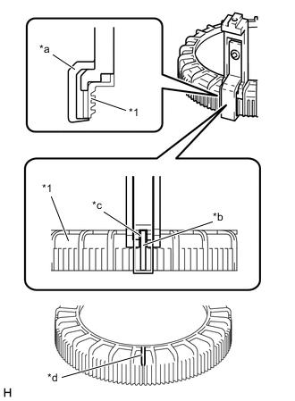
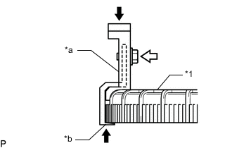
*1 Fuel Pump Gauge Retainer *a SST (claw set) *b Rib *c Cutout *d SST (Claw Set) Incorrect Installation Point (Rotational Start Point Mark of Fuel Pump Gauge Retainer) Set 4 SSTs (claw sets) to the fuel pump gauge retainer and temporarily install.
- SST
- 09808-14031 ( 09808-01080, 09808-01090, 09808-01100 )
Note
-
Align the cutout of SST (claw set) to the rib of the fuel pump gauge retainer.
-
Do not place SST on the rotational start point mark of the fuel pump gauge retainer, otherwise SST (claw set) cannot be set correctly.
-
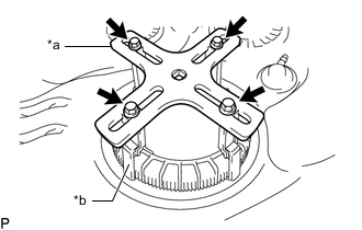
*1 Fuel Pump Gauge Retainer *a SST (Claw Set) *b Hook 
Press 
SST (Bolt) While firmly pressing the claw of SST into rib of the fuel pump gauge retainer, tighten the bolt.
-
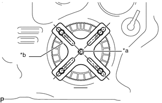
*a SST (Plate) *b SST (Claw Set) SST (Bolt) Temporarily install SST (plate) to SST (claw set) with 4 SSTs (bolts).
- SST
- 09808-14031 ( 09808-01030, 09808-01090 )
-
*a Center of Fuel Pump Gauge Retainer *b SST (Plate) Adjust the position of SST (plate) so that the setting hole of SST (handle) aligns with the center of the fuel pump gauge retainer.
-
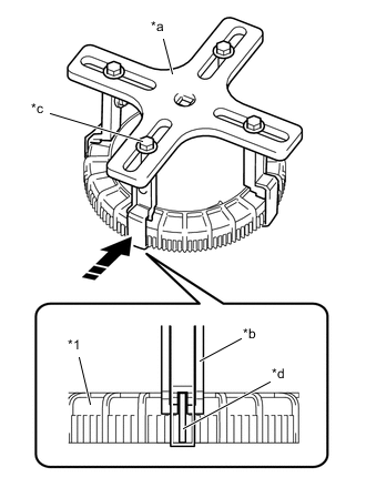
*1 Fuel Pump Gauge Retainer *a SST (Plate) *b SST (Claw Set) *c SST (Bolt) *d Rib 
Press While firmly pressing the SST (claw set) into rib of the fuel pump gauge retainer, tighten SST (bolt).
-
Install SST (handle) to SST (plate).
- SST
- 09808-14031 ( 09808-01010, 09808-01020 )
-
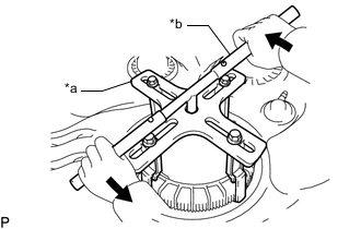
*a SST (Plate) *b SST (Handle) Loosen Slowly loosen the fuel pump gauge retainer by approximately 90°.
Note
-
Do not use any tools other than SST, such as a screwdriver, etc.
-
Do not use excessive force when pressing down on SST, as the fuel tank vent tube assembly will place excessive force on the pump gauge retainer and be difficult to remove, and parts may be damaged.
-
Do not use an impact wrench or turn the SST handle with excessive force, as parts may be damaged.
-
-
While one person slowly loosens the fuel pump gauge retainer, have another person press down the rising fuel tank vent tube assembly, securely attach the protrusion of the fuel tank vent tube assembly to the groove of the fuel tank sub-assembly, and then remove the fuel pump gauge retainer while making sure that the fuel tank vent tube assembly is properly aligned.
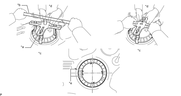
*a SST (Plate) *b SST (Handle) *c Person in Charge of Loosening *d Person in Charge of Supporting *e Co-rotation Prevention Check Mark - - Note
-
The fuel tank vent tube assembly is equipped with a spring that pushes against the bottom of the fuel tank sub-assembly to constantly lift the fuel tank vent tube assembly upwards.
-
If the fuel tank vent tube assembly and fuel tank sub-assembly are not firmly attached and the fuel pump gauge retainer is rotated, the fuel tank vent tube assembly will co-rotate and result in the fuel tank vent tube assembly and fuel tank sub-assembly being damaged.
-
Do not rotate the fuel pump gauge retainer when the co-rotation prevention check mark is out of place.
-
Do not bend the arm of the fuel sender gauge assembly.
-
-
Remove the gasket from the fuel tank sub-assembly.
-
-
REMOVE FUEL SUCTION WITH PUMP AND GAUGE TUBE ASSEMBLY (for Double Tank Type)
-
REMOVE NO. 3 FUEL TANK PROTECTOR
-
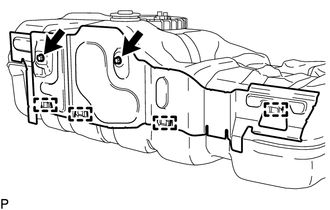
Remove the 2 bolts.
-
Detach the 4 clamps and remove the No. 3 fuel tank protector.
-
-
REMOVE FUEL TANK TO FILLER PIPE HOSE
-
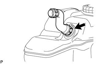
Loosen the clamp and remove the fuel tank to filler pipe hose from the fuel tank sub-assembly.
-