FUEL SUPPLY PUMP INSTALLATION

PROCEDURE
-
PRECAUTION
Note
-
When replacing the parts in the following chart (A), replace the No. 1 injection pipe subassembly, No. 2 injection pipe sub-assembly and/or fuel inlet pipe sub-assembly with new ones.
Replaced Parts (A) Pipes Requiring New Replacement
-
Injector assembly (including shuffling the injector assemblies between the cylinders)
-
Common rail assembly
-
Cylinder head sub-assembly
-
No. 1 injection pipe sub-assembly
-
No. 2 injection pipe sub-assembly
-
Supply pump assembly
-
Common rail assembly
-
Cylinder block sub-assembly
-
Cylinder head sub-assembly
-
Cylinder head gasket
-
Timing chain case assembly
-
No. 1 injection pipe sub-assembly
-
No. 2 injection pipe sub-assembly
-
Fuel inlet pipe sub-assembly
-
-
After removing the No. 1 injection pipe sub-assembly, No. 2 injection pipe sub-assembly and/or fuel inlet pipe sub-assembly, clean them with a brush and compressed air.
-
The injector assembly is a precision instrument. Do not use the injector assembly if it is struck or dropped.
-
Make sure foreign matter does not enter the fuel path.
-
-
INSTALL SUPPLY PUMP ASSEMBLY
Note
-
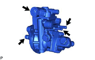
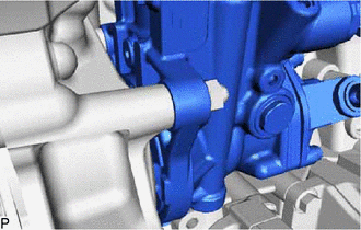
Do not hold the supply pump assembly by the parts indicated by the arrows in the illustration.
-
With SST set, do not turn the crankshaft more than a half rotation.
-
Apply a light coat of engine oil to a new O-ring.
-
Install the O-ring to the supply pump assembly.
-
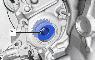
Text in Illustration *a Groove 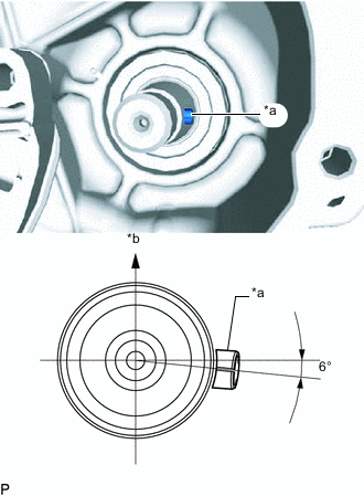
Text in Illustration *a Supply Pump Shaft Key *b Upper Side To insert the supply pump assembly shaft in the supply pump shaft sprocket, it may be necessary to turn the supply pump assembly several degrees and the groove in the supply pump assembly shaft are aligned.
Tech Tips
When installing a new supply pump assembly, adjust the supply pump assembly injection pump drive shaft key assignment by turning the supply pump assembly shown in the illustration.
-
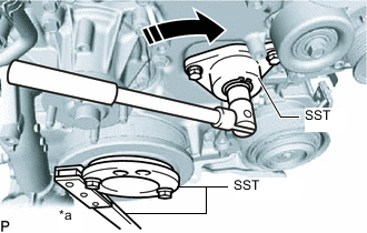
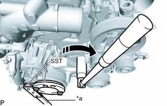
Text in Illustration *a Hold 
Turn Using SST, tighten clockwise direction the supply pump assembly, and then temporarily install the 3 fuel supply pump fixing nuts.
- SST
- 09213-58014 ( 91551-80840 )
- 09330-00021
- 09241-11010
-
Using SST, tighten and insert the supply pump assembly up to the position shown in the illustration and tighten the 3 fuel supply pump fixing nuts.
- Torque:
- 21 N*m { 214 kgf*cm, 15 ft.*lbf }
Tech Tips
After tightening the part with SST, a gap of 2 to 3 mm in area A shown in the illustration is normal.
-
Install the No. 1 fuel pump bracket with the 2 bolts to the supply pump assembly and cylinder block sub-assembly.
- Torque:
- 21 N*m { 214 kgf*cm, 15 ft.*lbf }
-
Remove SST and the 3 set bolts.
-
Text in Illustration *a Hold Turn Using SST, hold the crankshaft pulley subassembly and tighten the set nut.
- SST
- 09213-58014 ( 91551-80840 )
- 09330-00021
- Torque:
- 137 N*m { 1397 kgf*cm, 101 ft.*lbf }
-
-
INSTALL TIMING CHAIN COVER PLATE
-
Install the timing chain cover plate and new gasket with the 3 bolts.
- Torque:
- 10 N*m { 102 kgf*cm, 7 ft.*lbf }
-
-
INSTALL FUEL PUMP MOTOR WIRE
-
Attach the clamp and install the fuel pump motor wire.
-
Connect the fuel pump motor wire connector.
-
-
INSTALL FUEL INJECTION PUMP COVER SUB-ASSEMBLY
-
Install the fuel injection pump cover sub-assembly to the supply pump assembly.
-
-
INSTALL NO. 1 FUEL HOSE
-
Install the No. 1 fuel hose to the supply pump assembly and No. 2 fuel pipe, and slide the 2 clamps to secure it.
-
-
INSTALL NO. 2 FUEL HOSE
-
Install the No. 2 fuel hose to the supply pump assembly and No. 3 nozzle leakage pipe assembly, and slide the 2 clamps to secure it.
-
-
INSTALL V-RIBBED BELT TENSIONER ASSEMBLY
-
CONNECT NO. 3 ENGINE WIRE (for Cold Area Specification Vehicles)
-
INSTALL FAN SHROUD
-
INSTALL RADIATOR RESERVOIR ASSEMBLY
-
INSTALL NO. 1 RADIATOR HOSE
-
INSTALL NO. 2 INTERCOOLER AIR HOSE
-
INSTALL INTERCOOLER AIR HOSE
-
INSTALL INTAKE MANIFOLD
-
CONNECT CABLE TO NEGATIVE BATTERY TERMINAL
Note
When disconnecting the cable, some systems need to be initialized after the cable is reconnected.
-
BLEED AIR FROM FUEL SYSTEM
-
INSPECT FOR FUEL LEAK
-
INSTALL NO. 1 ENGINE UNDER COVER SUB-ASSEMBLY