FUEL INJECTOR INSTALLATION

CAUTION / NOTICE / HINT
Note
-
When replacing the parts in the following chart (A), replace the No. 1 injection pipe subassembly, No. 2 injection pipe sub-assembly and/or fuel inlet pipe sub-assembly with new ones.
Replaced Parts (A) Pipes Requiring New Replacement
-
Injector assembly (including shuffling the injector assemblies between the cylinders)
-
Common rail assembly
-
Cylinder head sub-assembly
-
No. 1 injection pipe sub-assembly
-
No. 2 injection pipe sub-assembly
-
Supply pump assembly
-
Common rail assembly
-
Cylinder block sub-assembly
-
Cylinder head sub-assembly
-
Cylinder head gasket
-
Timing chain case assembly
-
No. 1 injection pipe sub-assembly
-
No. 2 injection pipe sub-assembly
-
Fuel inlet pipe sub-assembly
-
-
After removing the No. 1 injection pipe sub-assembly, No. 2 injection pipe sub-assembly and/or fuel inlet pipe sub-assembly, clean them with a brush and compressed air.
-
The injector assembly is a precision instrument. Do not use the injector assembly if it is struck or dropped.
-
Make sure foreign matter does not enter the fuel path.
PROCEDURE
-
INSTALL NOZZLE HOLDER GASKET
-
Install 4 new nozzle holder gaskets to the cylinder head cover sub-assembly.
-
-
TEMPORARILY INSTALL INJECTOR ASSEMBLY
Tech Tips
Before installing the injector assembly, check for carbon, foreign matter, etc. on the seal surfaces of the cylinder head sub-assembly and injector assembly. If there is foreign matter, remove it before installing the injector assembly.
-
Install 4 new injection nozzle seats to the cylinder head sub-assembly.
-
Apply a light coat of engine oil to the O-ring on each injector assembly.
-
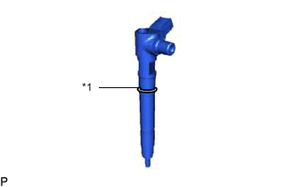
Text in Illustration *1 O-Ring Install a new O-ring to each injector assembly.
-
Install the 4 injector assemblies to the cylinder head sub-assembly.
Note
Fit the injector assembly to the injection nozzle seats.
-
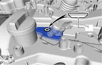
Text in Illustration *1 Washer Install the nozzle holder clamps and washers as shown in the illustration.
Note
Pay attention to the mounting orientation (beveled edge) of the washer.
-
Temporarily install the nozzle holder clamp bolts.
Note
When temporarily installing the nozzle holder clamp bolt to the No. 1 nozzle holder clamp, make sure that the bolt and clamp are not at an angle.
Tech Tips
Apply a light coat of engine oil to the threads of the nozzle holder clamp bolts.
-
-
TEMPORARILY INSTALL NO. 1 AND NO. 2 INJECTION PIPE SUBASSEMBLY
-
Temporarily install the 2 No. 2 injection pipe sub-assemblies 4 union nuts.
-
Temporarily install the 2 No. 1 injection pipe sub-assemblies 4 union nuts.
-
-
TIGHTEN INJECTOR ASSEMBLY
-
Tighten the 4 nozzle holder clamp bolts.
- Torque:
- 21 N*m { 214 kgf*cm, 15 ft.*lbf }
-
-
TIGHTEN NO. 1 AND NO. 2 INJECTION PIPE SUB-ASSEMBLY
-
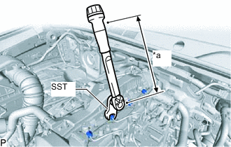
Text in Illustration *a Torque Wrench Fulcrum Length Using SST, tighten the No. 1 and No. 2 injection pipe sub-assemblies 8 union nuts.
- Torque:
- Specified tightening torque
- 40 N*m { 214 kgf*cm, 15 ft.*lbf }
Tech Tips
-
Calculate the torque wrench reading when changing the fulcrum length of the torque wrench.
-
When using SST (fulcrum length of 50 mm (1.97 in.)) + torque wrench (fulcrum length of 180 mm (7.09 in.)): 31 N*m (316 kgf*cm, 23 ft.*lbf)
-
-
INSTALL NOZZLE LEAKAGE PIPE ASSEMBLY
-
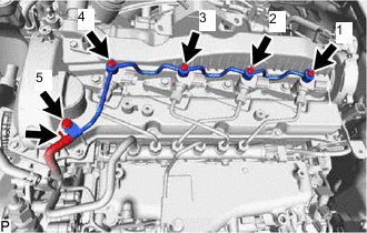
Temporarily install the nozzle leakage pipe assembly and 4 new gaskets with the 4 union bolts and bolt.
-
Tighten the 4 union bolts and bolt in the order shown in the illustration.
- Torque:
- 12 N*m { 122 kgf*cm, 9 ft.*lbf }
-
Connect the No. 5 fuel hose to the nozzle leakage pipe assembly.
-
-
INSTALL HARNESS BRACKET
-
Install the harness bracket with the bolt.
- Torque:
- 8.4 N*m { 86 kgf*cm, 74 in.*lbf }
-
-
INSTALL WIRING HARNESS CLAMP BRACKET
-
Install the wiring harness clamp bracket with bolt to the cylinder head cover sub-assembly.
- Torque:
- 10 N*m { 102 kgf*cm, 7 ft.*lbf }
-
Connect the pressure discharge valve connector to the common rail assembly.
-
-
INSTALL NO. 1 FUEL PIPE
-
INSTALL EGR COOLER ASSEMBLY
-
CONNECT CABLE TO NEGATIVE BATTERY TERMINAL
Note
When disconnecting the cable, some systems need to be initialized after the cable is reconnected. Click here
-
PERFORM REGISTRATION
-
Perform registration of injector compensation codes. Click here
-
Perform registration of pilot quantity learning. Click here
-
-
BLEED AIR FROM FUEL SYSTEM
-
INSPECT FOR FUEL LEAK