FUEL INJECTOR INSTALLATION

CAUTION / NOTICE / HINT
Note
-
When replacing the injectors (including shuffling the injectors between the cylinders), common rail or cylinder head, it is necessary to replace the injection pipes with new ones.
-
When replacing the fuel supply pump, common rail, cylinder block, cylinder head, cylinder head gasket or timing gear case, it is necessary to replace the fuel inlet pipe with a new one.
-
After removing the injection pipes, clean them with a brush and compressed air.
PROCEDURE
-
INSTALL INJECTOR ASSEMBLY
Note
Be sure to install the injector, No. 1 nozzle holder clamp, washer and bolt in their original positions.
-
Install 4 new injection nozzle seats to the cylinder head.
-
Apply a small amount of clean engine oil to 4 new O-rings.
-
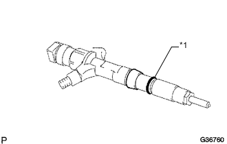
Text in Illustration *1 New O-Ring Install an O-ring to each injector as shown in the illustration.
-
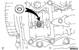
Insert the 4 injectors into the cylinder head.
Note
-
Insert the injector until it touches the injection nozzle seat surface.
-
After installing the injector to the cylinder head, the O-ring may prevent the injector from fully seating. If so, pull out the injector and reinstall it.
-
Always return an injector to the same place it was removed from.
-
-
For an injector that has been replaced with a new injector, register the injector compensation code Click here.
-
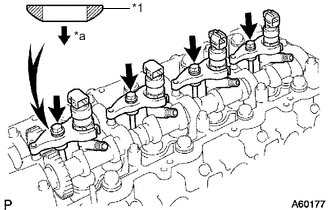
Text in Illustration *1 Washer *a Downward Temporarily install 4 new washers and the 4 No. 1 nozzle holder clamps with the 4 bolts.
Tech Tips
Apply a small amount of engine oil to the threads and under the heads of the clamp bolts.
-
Temporarily install the 4 injection pipes with the union nuts.
Tech Tips
To position the injectors, loosely tighten the union nut.
-
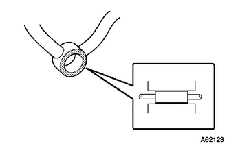
Check the nozzle leakage pipe. Check that there are no scratches or dents on the 5 union seal surfaces.
If scratches or dents are present, replace the nozzle leakage pipe.
-
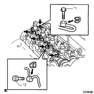
Text in Illustration *1 Union Bolt *2 Hollow Screw Set the leakage pipe and 5 new gaskets in place.
-
Apply a small amount of oil to the 4 injector hollow screws and union bolt.
-
Temporarily install the leakage pipe with the 4 injector hollow screws and union bolt.
-
Tighten the 4 holder clamp bolts.
- Torque:
- 22 N*m { 220 kgf*cm, 16 ft.*lbf }
-
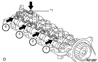
Text in Illustration *1 Union Bolt Tighten the 4 hollow screws in order from 1 to 4.
- Torque:
- 16 N*m { 163 kgf*cm, 12 ft.*lbf }
Note
If a hollow screw is accidentally tightened beyond the torque specification, it must be replaced.
-
Tighten the union bolt.
- Torque:
- 13 N*m { 127 kgf*cm, 9 ft.*lbf }
Note
If the union bolt is accidentally tightened beyond the torque specification, it must be replaced.
-
Remove the 4 injection pipes.
-
-
INSPECT FOR FUEL LEAK
-
Check that there are no leaks from the nozzle leakage pipe connection.
-
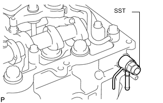
Install the gasket and No. 2 nozzle leakage pipe to the cylinder head with SST (check valve).
Part No. 23762-27010 (No. 2 nozzle leakage pipe) 90904-30012 (Gasket) - SST
- 09280-00010
- Torque:
- 21 N*m { 214 kgf*cm, 15 ft.*lbf }
-
Apply a small amount of soapy water (or other fluid for detecting fuel leakage) on the nozzle leakage pipe connection.
-
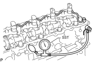
Install SST (turbocharger pressure gauge) to the fuel return side of the leakage pipe, maintain 100 kPa (1.0 kgf/cm2, 15 psi) of pressure for 60 seconds and check that no bubbles form.
- SST
- 09992-00242
-
After checking for fuel leaks, wipe off the soapy water from the leakage pipe connection.
-
Remove SST, the No. 2 nozzle leakage pipe and gasket.
Note
Never reinstall the disassembled union bolt to the engine.
-
-
-
INSTALL CYLINDER HEAD COVER SUB-ASSEMBLY
-
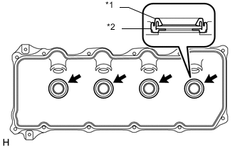
Text in Illustration *1 No. 3 Cylinder Head Cover Gasket *2 Cylinder Head Cover Install 4 new No. 3 cylinder head cover gaskets to the cylinder head cover in the directions shown in the illustration.
Note
-
Do not install the No. 3 cylinder head cover gaskets at an angle.
-
Check that there is no foreign matter at the installation location of the No. 3 cylinder head cover gaskets.
-
-
Remove any old seal packing (FIPG material) from the cylinder head.
-
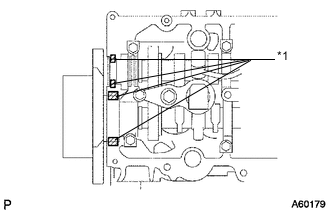
Text in Illustration *1 Seal Packing Apply seal packing to the specific areas shown in the illustration.
Seal packing Toyota Genuine Seal Packing Black, Three Bond 1207B or equivalent Note
-
Remove any oil from the contact surface.
-
Install the head cover within 3 minutes after applying seal packing.
-
Do not start the engine for at least 2 hours after installing the seal packing.
-
-
Install a new cylinder head cover gasket and the cylinder head cover with the 10 bolts and 2 nuts.
- Torque:
- 9.0 N*m { 92 kgf*cm, 80 in.*lbf }
-
Install 4 new nozzle holder seals.
-
-
INSTALL NO. 2 CYLINDER HEAD COVER SUB-ASSEMBLY
-
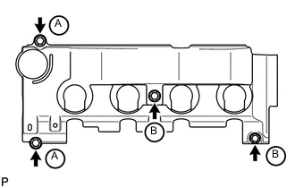
Install the No. 2 cylinder head cover with the 4 bolts.
- Torque:
- for bolt A
- 18 N*m { 184 kgf*cm, 13 ft.*lbf }
- for bolt B
- 8.0 N*m { 82 kgf*cm, 71 in.*lbf }
-
Attach the 2 wire harness clamps and connect the wire harness to the No. 2 cylinder head cover.
-
Connect the 4 injector connectors.
-
-
INSTALL VENTILATION PIPE
-
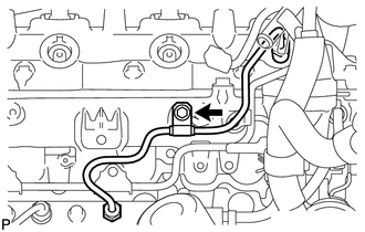
INSTALL NO. 2 NOZZLE LEAKAGE PIPE ASSEMBLY
-
INSTALL OIL FILTER SUB-ASSEMBLY
-
INSTALL NO. 4 INJECTION PIPE SUB-ASSEMBLY
Note
-
When replacing an injector, it is necessary to replace the 4 injection pipes with new ones.
-
Keep the joints of the injection pipe clean.
-
Temporarily install the No. 4 injection pipe with the union nuts.
-
Install the bolt.
- Torque:
- 5.0 N*m { 51 kgf*cm, 44 in.*lbf }
Note
-
If an injection pipe clamp is removed from the No. 4 injection pipe, replace the injection clamp with a new one.
-
Make sure that the inner-rubbers of the injection pipe fit inside the clamps.
-
When installing the pipe, check that the inner-rubbers and the clamps are in their proper positions.
-
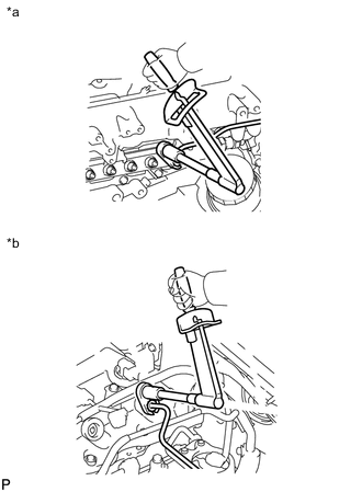
Text in Illustration *a Common Rail Side *b Injector Side Using a 17 mm union nut wrench, tighten the injection pipe union nut on the common rail side.
- Torque:
- 35 N*m { 357 kgf*cm, 26 ft.*lbf }
Note
Use the formula to calculate special torque values for situations where a union nut wrench is combined with a torque wrench Click here.
-
Using a 17 mm union nut wrench, tighten the injection pipe union nuts on the injector side.
- Torque:
- 35 N*m { 357 kgf*cm, 26 ft.*lbf }
Note
Use the formula to calculate special torque values for situations where a union nut wrench is combined with a torque wrench Click here.
-
-
INSTALL MANIFOLD STAY WITH VACUUM SWITCHING VALVE
-
INSTALL INTAKE AIR CONNECTOR WITH DIESEL THROTTLE BODY ASSEMBLY (w/o EGR System)
-
CONNECT ENGINE WIRE (w/o EGR System)
-
INSTALL AIR CONNECTOR STAY (w/o EGR System)
-
INSTALL NO. 1, NO. 2 AND NO. 3 INJECTION PIPE SUB-ASSEMBLY (w/o EGR System)
Note
-
When replacing an injector, it is necessary to replace the 4 injection pipes with new ones.
-
Keep the joints of the injection pipe clean.
-
Temporarily install the No. 1, No. 2 and No. 3 injection pipes with the union nuts.
-
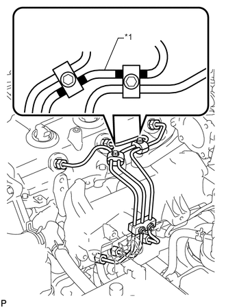
Text in Illustration *1 No. 2 Injection Pipe Install the No. 2 and No. 3 injection pipe clamps with the 2 bolts and 2 nuts as shown in the illustration.
- Torque:
- 5.0 N*m { 51 kgf*cm, 44 in.*lbf }
Tech Tips
If the painted mark on the No. 2 injection pipe has disappeared, use the illustration as a reference to install the clamps.
-
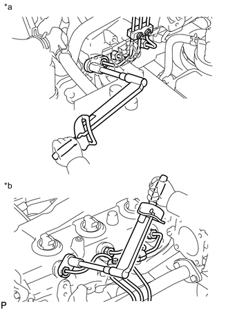
Text in Illustration *a Common Rail Side *b Injector Side Using a 17 mm union nut wrench, tighten the injection pipe union nuts on the common rail side.
- Torque:
- 35 N*m { 357 kgf*cm, 26 ft.*lbf }
Note
Use the formula to calculate special torque values for situations where a union nut wrench is combined with a torque wrench Click here.
-
Using a 17 mm union nut wrench, tighten the injection pipe union nuts on the injector side.
- Torque:
- 35 N*m { 357 kgf*cm, 26 ft.*lbf }
Note
Use the formula to calculate special torque values for situations where a union nut wrench is combined with a torque wrench Click here.
-
-
INSTALL THROTTLE BODY BRACKET (w/o EGR System)
-
INSTALL NO. 1 INTAKE PIPE (w/o EGR System)
-
CONNECT NO. 4 VACUUM TRANSMITTING PIPE SUB-ASSEMBLY (w/o EGR System)
-
CONNECT INLET HEATER WATER HOSE (w/o EGR System)
-
INSTALL ELECTRIC EGR CONTROL VALVE ASSEMBLY (w/ EGR System)
-
Install the electric EGR control valve assembly Click here.
-
-
PERFORM REGISTRATION
-
Perform registration of the injector compensation code Click here.
-
Perform registration of pilot quantity learning Click here.
-
-
CONNECT CABLE TO NEGATIVE BATTERY TERMINAL
Note
When disconnecting the cable, some systems need to be initialized after the cable is reconnected Click here.
-
ADD ENGINE COOLANT (w/ EGR System with EGR Cooler)
-
BLEED AIR FROM FUEL SYSTEM
-
INSPECT FOR COOLANT LEAK (w/ EGR System with EGR Cooler)
-
INSPECT FOR FUEL LEAK
-
INSPECT FOR OIL LEAK
-
INSPECT ENGINE OIL LEVEL