OIL PUMP INSTALLATION
PROCEDURE
-
INSTALL TIMING CHAIN CASE ASSEMBLY AND ENGINE WATER PUMP ASSEMBLY
-
Apply a light coat of engine oil to the 4 new O-rings.
-
Install the 4 O-rings to the cylinder block sub-assembly and cylinder head sub-assembly.
-
Clean and degrease the contact surfaces of the timing chain case assembly, cylinder head sub-assembly and cylinder block sub-assembly.
-
Apply a coating of seal packing to the timing chain case assembly at the points shown in the illustration.
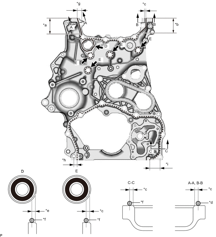
Text in Illustration *a 46 mm (1.81 in.) *b 50 mm (1.97 in.) *c 2.0 to 3.0 mm (0.0787 to 0.118 in.) *d 2.5 to 3.5 mm (0.0984 to 0.138 in.) *e 3.0 to 4.0 mm (0.118 to 0.158 in.) *f 1.5 to 2.5 mm (0.0591 to 0.0984 in.) *g 13 to 15 mm (0.512 to 0.591 in.) *h 9.0 to 11 mm (0.354 to 0.433 in.) *i 31 to 33 mm (1.22 to 1.30 in.) - - Seal packing for line area D Toyota Genuine Seal Packing 1282B, Three Bond 1282B or equivalent. for line area A-A, B-B, C-C and E Toyota Genuine Seal Packing Black, Three Bond 1207B or equivalent. Line Type and Area Seal Packing Diameter Application Area Seal Packing Application Length Dashed Line 1.5 to 2.5 mm (0.0591 to 0.0984 in.) 2.0 to 3.0 mm (0.0787 to 0.118 in.) - A - A 2.5 to 3.5 mm (0.0984 to 0.138 in.) 2.0 to 3.0 mm (0.0787 to 0.118 in.) 46 mm (1.81 in.) B - B 2.5 to 3.5 mm (0.0984 to 0.138 in.) 2.0 to 3.0 mm (0.0787 to 0.118 in.) 50 mm (1.97 in.) D 1.5 to 2.5 mm (0.0591 to 0.0984 in.) 3.0 to 4.0 mm (0.118 to 0.158 in.) - Note
-
Using non-residue solvent, clean and remove any oil from the installation surface.
-
Install the part within 3 minutes and tighten the bolts within 10 minutes after applying seal packing.
-
Do not add engine oil for at least 2 hours after installation.
-
Do not start the engine within 2 hours after installation.
-
-
Temporarily install the timing chain case assembly with the 15 bolts.
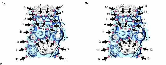
Text in Illustration *a Type of bolt *b Tightening Bolt Length Item Length Thread Diameter Bolt A 30 mm (1.18 in.) 8.0 mm (0.315 in.) Bolt B 45 mm (1.77 in.) 8.0 mm (0.315 in.) Bolt C 65 mm (2.56 in.) 8.0 mm (0.315 in.) Bolt D 30 mm (1.18 in.) 10 mm (0.394 in.) -
Temporarily install a new gasket and the engine water pump assembly with the 8 bolts.
-
Tighten the 23 bolts in the order shown in the illustration.
- Torque:
- for bolt A, B and C
- 25 N*m { 255 kgf*cm, 18 ft.*lbf }
- for bolt D
- 43 N*m { 438 kgf*cm, 32 ft.*lbf }
Note
Check the torque of bolt 1 after tightening bolt 23.
-
-
INSTALL INJECTION PUMP INSULATOR
-
INSTALL SUPPLY PUMP ASSEMBLY
-
INSTALL NO. 1 CHAIN TENSIONER SLIPPER
-
TEMPORARILY INSTALL NO. 1 CHAIN VIBRATION DAMPER
-
INSTALL CRANKSHAFT TIMING GEAR OR SPROCKET, INJECTION PUMP DRIVE GEAR WITH NO. 1 CHAIN SUB-ASSEMBLY
-
TIGHTEN NO. 1 CHAIN VIBRATION DAMPER
-
INSTALL NO. 1 CHAIN TENSIONER ASSEMBLY
-
INSTALL SUPPLY PUMP SHAFT NUT
-
INSTALL CAMSHAFT TIMING SPROCKET
-
INSTALL NO. 2 CHAIN VIBRATION DAMPER
-
INSTALL NO. 2 CHAIN SUB-ASSEMBLY
-
INSTALL NO. 2 CHAIN TENSIONER SLIPPER
-
INSTALL NO. 2 CHAIN TENSIONER ASSEMBLY
-
INSTALL TIMING CHAIN GUIDE
-
CHECK NO. 1 CYLINDER TO TDC/COMPRESSION
-
INSTALL BALANCE SHAFT TIMING SPROCKET, BALANCE SHAFT TIMING GEAR AND NO. 3 CHAIN SUB-ASSEMBLY
-
INSTALL NO. 1 BALANCE SHAFT THRUST PLATE
-
INSTALL NO. 3 CHAIN TENSIONER ASSEMBLY
-
INSTALL OIL PUMP DRIVE GEAR
-
Install the oil pump drive gear to the crankshaft.
-
-
INSTALL TIMING CHAIN COVER PLATE
-
INSTALL TIMING CHAIN COVER SUB-ASSEMBLY
-
Apply a light coat of engine oil to a new timing chain case gasket.
-
Install the timing chain case gasket to the timing chain case assembly.
-
Clean and degrease the contact surfaces of the timing chain cover sub-assembly and timing chain case assembly.
-
Apply a coating of seal packing to the timing chain cover sub-assembly at the points shown in the illustration.
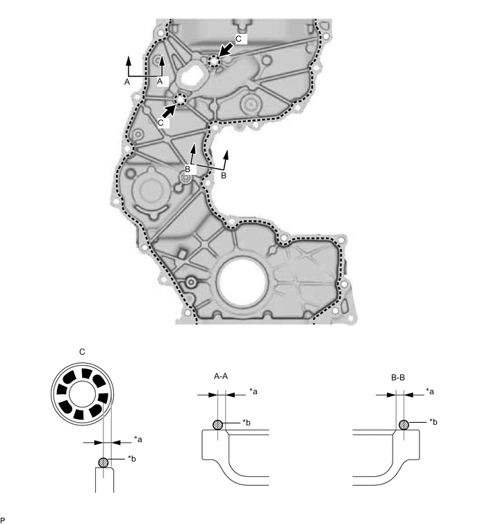
Text in Illustration *a 2.0 to 3.0 mm (0.0787 to 0.118 in.) *b 2.5 to 3.5 mm (0.0984 to 0.138 in.) Seal packing Toyota Genuine Seal Packing Black, Three Bond 1207B or equivalent. Standard seal packing diameter 2.5 to 3.5 mm (0.0984 to 0.138 in.) Note
-
Using non-residue solvent, clean and remove any oil from the installation surface.
-
Install the part within 3 minutes and tighten the bolts within 10 minutes after applying seal packing.
-
Do not add engine oil for at least 2 hours after installation.
-
Do not start the engine within 2 hours after installation.
-
-
Temporarily install the timing chain cover sub-assembly with the 20 bolts.
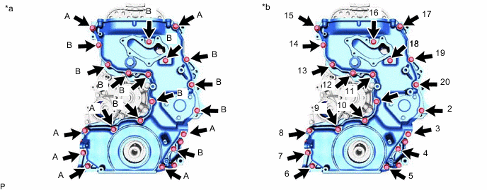
Text in Illustration *a Type of bolt *b Tightening Bolt Length Item Length Thread Diameter Bolt A 40 mm (1.57 in.) 8.0 mm (0.315 in.) Bolt B 25 mm (0.984 in.) 8.0 mm (0.315 in.) -
Tighten the 20 bolts in the order shown in the illustration.
- Torque:
- 21 N*m { 214 kgf*cm, 15 ft.*lbf }
Note
Check the torque of bolt 1 after tightening bolt 20.
-
-
INSTALL FRONT CRANKSHAFT OIL SEAL
-
INSTALL OIL PAN SUB-ASSEMBLY
-
Clean and degrease the contact surfaces of the oil pan sub-assembly and cylinder block sub-assembly.
-
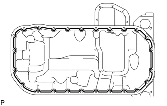
Apply seal packing in a continuous line as shown in the illustration.
Text in Illustration 
Seal Packing Seal packing Toyota Genuine Seal Packing Black, Three Bond 1207B or equivalent Standard seal diameter 3.5 to 4.5 mm (0.138 to 0.177 in.) Note
-
Remove any oil from the contact surface.
-
Install the oil pan sub-assembly within 3 minutes and tighten the bolts and nuts within 10 minutes after applying seal packing.
-
Do not add engine oil within 2 hours after installation.
-
Do not start the engine for at least 2 hours after installation.
-
-
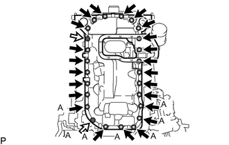
Install the oil pan sub-assembly to the cylinder block sub-assembly with the 23 bolts and 2 nuts.
- Torque:
- 10 N*m { 102 kgf*cm, 7 ft.*lbf }
Note
Check the torque of all nuts and bolts labeled A again.
-
-
INSTALL NO. 2 OIL PAN SUB-ASSEMBLY
-
Clean and degrease the contact surfaces of the No. 2 oil pan sub-assembly and cylinder block sub-assembly.
-
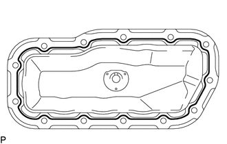
Apply seal packing in a continuous line as shown in the illustration.
Text in Illustration Seal Packing Seal packing Toyota Genuine Seal Packing Black, Three Bond 1207B or equivalent Standard seal diameter 3.5 to 4.5 mm (0.138 to 0.177 in.) Note
-
Remove any oil from the contact surface.
-
Install the No. 2 oil pan sub-assembly within 3 minutes and tighten the bolts and nuts within 10 minutes after applying seal packing.
-
Do not add engine oil within 2 hours after installation.
-
Do not start the engine for at least 2 hours after installation.
-
-
Install the No. 2 oil pan sub-assembly to the oil pan sub-assembly with the 11 bolts and 2 nuts.
- Torque:
- 10 N*m { 102 kgf*cm, 7 ft.*lbf }
-
-
INSTALL ENGINE OIL LEVEL SENSOR
-
INSTALL CYLINDER HEAD COVER SUB-ASSEMBLY
-
Apply a light coat of engine oil to the O-ring of the camshaft position sensor.
-
Install a new cylinder head cover gasket, No. 2 cylinder head cover gasket and 2 camshaft bearing cap oil hole gaskets to the cylinder head cover sub-assembly.
-
Clean and degrease the contact surfaces of the cylinder head cover sub-assembly and cylinder head sub-assembly.
-
Apply seal packing as shown in the illustration.
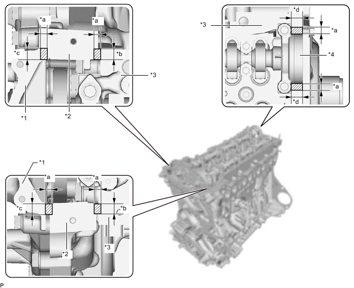
Text in Illustration *1 Timing Chain Cover Sub-assembly *2 Timing Chain Case Assembly *3 Cylinder Head Sub-assembly *4 No. 3 Camshaft Bearing Cap *a Seal Diameter: 3.0 to 6.0 mm (0.118 to 0.236 in.) *b Application Width: 7.0 mm (0.276 in.) *c Application Width: 9.0 mm (0.354 in.) *d Application Width: 11.0 mm (0.433 in.) Seal packing Toyota Genuine Seal Packing Black, Three Bond 1207B or equivalent Standard seal diameter 3.0 to 6.0 mm (0.118 to 0.236 in.) Note
-
Remove any oil from the contact surface.
-
Install the cylinder head cover sub-assembly within 3 minutes and tighten the bolts within 10 minutes after applying seal packing.
-
Do not add engine oil for at least 2 hours after installation.
-
Do not start the engine within 2 hours after installation.
-
-
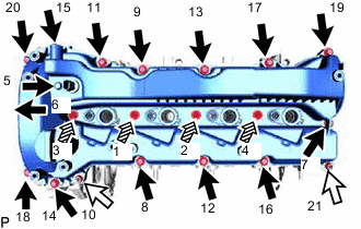
Tighten the 14 bolts, 4 nozzle holder clamp seats, 2 nuts and camshaft position sensor in the order shown in the illustration.
Text in Illustration Bolt 
Nut 
Nozzle Holder Clamp Seat - Torque:
- 10 N*m { 107 kgf*cm, 7 ft.*lbf }
Note
-
When reusing the camshaft position sensor, check the O-rings.
-
Make sure that the O-ring is not cracked or jammed when installing it on the cylinder head cover sub-assembly.
-
Replace with a new part if it is dropped or if it receives a strong impact.
-
Check the torque of bolts 1 to 4 again.
-
-
INSTALL NOZZLE HOLDER GASKET
-
TEMPORARILY INSTALL INJECTOR ASSEMBLY
-
INSTALL GENERATOR BRACKET SUB-ASSEMBLY
-
INSTALL NO. 1 ENGINE HANGER
-
INSTALL NO. 1 WATER HOSE CLAMP BRACKET
-
INSTALL CRANKSHAFT PULLEY
-
INSTALL CRANKSHAFT PULLEY COVER
-
INSTALL VISCOUS HEATER CRANKSHAFT PULLEY (w/ Viscous Heater)
-
INSTALL V-RIBBED BELT TENSIONER ASSEMBLY
-
Install the V-ribbed belt tensioner assembly to the timing chain cover sub-assembly with 3 bolts.
- Torque:
- 21 N*m { 214 kgf*cm, 15 ft.*lbf }
-
-
INSTALL NO. 1 IDLER PULLEY SUB-ASSEMBLY
-
Install the No. 1 idler pulley sub-assembly to the generator bracket sub-assembly with the bolt.
- Torque:
- 43 N*m { 438 kgf*cm, 32 ft.*lbf }
-
-
INSTALL THERMOSTAT
-
INSTALL WATER INLET
-
INSTALL WATER OUTLET SUB-ASSEMBLY
-
INSTALL NO. 2 WATER BY-PASS PIPE SUB-ASSEMBLY
-
TEMPORARILY INSTALL TURBO OIL INLET PIPE SUB-ASSEMBLY
-
TEMPORARILY INSTALL EXHAUST MANIFOLD WITH TURBOCHARGER SUB-ASSEMBLY
-
INSTALL TURBO OIL OUTLET PIPE
-
TEMPORARILY INSTALL TURBOCHARGER STAY
-
TIGHTEN EXHAUST MANIFOLD WITH TURBOCHARGER SUB-ASSEMBLY
-
TIGHTEN TURBOCHARGER STAY
-
INSTALL NO. 1 VISCOUS HEATER BRACKET SUB-ASSEMBLY (w/ Viscous Heater)
-
CONNECT NO. 1 AND NO.2 TURBO WATER HOSE
-
INSTALL NO. 1 WATER BY-PASS PIPE
-
INSTALL NO. 3 WATER BY-PASS PIPE
-
INSTALL EXHAUST MANIFOLD CONVERTER SUB-ASSEMBLY
-
INSTALL NO. 2 EXHAUST PIPE SUPPORT STAY
-
INSTALL NO. 1 TURBO INSULATOR
-
INSTALL NO. 1 EXHAUST MANIFOLD HEAT INSULATOR
-
INSTALL AIR FUEL RATIO SENSOR
-
INSTALL NO. 2 EXHAUST MANIFOLD HEAT INSULATOR
-
INSTALL NO. 1 INJECTOR HOLDER
-
CONNECT NO. 4 WATER BY-PASS HOSE
-
INSTALL NO. 5 WATER BY-PASS HOSE
-
INSTALL PCV PIPE (for Cold Area Specification Vehicles)
-
INSTALL PCV HOSE (except Cold Area Specification Vehicles)
-
INSTALL NO. 1 COMPRESSOR MOUNTING BRACKET
-
INSTALL NO. 3 FUEL PIPE
-
INSTALL HOSE BRACKET
-
INSTALL NO. 1 AND NO. 2 INJECTION PIPE SUB-ASSEMBLY
-
TIGHTEN INJECTOR ASSEMBLY
-
TIGHTEN NO. 1 AND NO. 2 INJECTION PIPE SUB-ASSEMBLY
-
INSTALL WIRING HARNESS CLAMP BRACKET
-
INSTALL NOZZLE LEAKAGE PIPE ASSEMBLY
-
INSTALL NO. 1 FUEL PIPE
-
INSTALL WIRING HARNESS CLAMP BRACKET
-
INSTALL INTAKE MANIFOLD
-
INSTALL NO. 2 NOZZLE LEAKAGE PIPE ASSEMBLY
-
INSTALL FUEL INLET PIPE SUB-ASSEMBLY
-
INSTALL NO. 1 FUEL HOSE
-
INSTALL NO. 2 FUEL HOSE
-
INSTALL NO. 4 FUEL PIPE SUB-ASSEMBLY
-
INSTALL FUEL PUMP MOTOR WIRE
-
INSTALL FUEL INJECTION PUMP COVER SUB-ASSEMBLY
-
INSTALL MANIFOLD STAY
-
INSTALL WIRING HARNESS CLAMP BRACKET
-
INSTALL NO. 2 FUEL PIPE
-
INSTALL ENGINE OIL LEVEL DIPSTICK GUIDE
-
INSTALL NO. 1 EGR COOLER AND NO. 2 EGR VALVE ASSEMBLY WITH ELECTRIC EGR CONTROL VALVE ASSEMBLY
-
INSTALL NO. 4 WATER BY-PASS PIPE SUB-ASSEMBLY
-
INSTALL VACUUM CONTROL VALVE SET
-
INSTALL NO. 1 EGR PIPE SUB-ASSEMBLY
-
INSTALL CONNECTING WIRE
-
INSTALL NO. 3 WATER BY-PASS PIPE SUB-ASSEMBLY
-
INSTALL NO. 2 EGR PIPE
-
INSTALL EGR VALVE BRACKET
-
INSTALL DIESEL TURBO PRESSURE SENSOR
-
INSTALL GAS FILTER
-
INSTALL ENGINE COVER BRACKET
-
INSTALL PIPE CLAMP
-
TEMPORARILY INSTALL NO. 2 VACUUM PIPE
-
TEMPORARILY INSTALL NO. 1 VACUUM PIPE
-
TIGHTEN NO. 2 VACUUM PIPE
-
TIGHTEN NO. 1 VACUUM PIPE
-
INSTALL EXHAUST GAS TEMPERATURE SENSOR
-
INSTALL DIFFERENTIAL PRESSURE SENSOR
-
INSTALL NO. 2 WATER BY-PASS PIPE
-
INSTALL DIESEL THROTTLE BODY ASSEMBLY
-
INSTALL AIR TUBE ASSEMBLY
-
INSTALL ENGINE WIRE
-
INSTALL NO. 2 ENGINE COVER BRACKET
-
INSTALL NO. 3 ENGINE COVER BRACKET
-
Install the No. 3 engine cover bracket to the No. 2 engine cover bracket and engine cover bracket with the 2 bolts.
- Torque:
- 21 N*m { 214 kgf*cm, 15 ft.*lbf }
-
-
INSTALL ENGINE ASSEMBLY