OIL PUMP REMOVAL
CAUTION / NOTICE / HINT
Note
-
When replacing the parts in the following chart (A), replace the No. 1 injection pipe sub-assembly, No. 2 injection pipe sub-assembly and/or fuel inlet pipe sub-assembly with new ones.
Replaced Parts (A) Pipes Requiring New Replacement
-
Injector assembly (including shuffling the injector assemblies between the cylinders)
-
Common rail assembly
-
Cylinder head sub-assembly
-
No. 1 injection pipe sub-assembly
-
No. 2 injection pipe sub-assembly
-
Supply pump assembly
-
Common rail assembly
-
Cylinder block sub-assembly
-
Cylinder head sub-assembly
-
Cylinder head gasket
-
Timing chain case assembly
Fuel inlet pipe sub-assembly -
-
After removing the No. 1 injection pipe sub-assembly, No. 2 injection pipe sub-assembly and/or fuel inlet pipe sub-assembly, clean them with a brush and compressed air.
-
The injector assembly is a precision instrument. Do not use the injector assembly if it is struck or dropped.
-
Make sure foreign matter does not enter the fuel path.
-
The supply pump assembly is a precision instrument. Do not use the supply pump assembly if it is struck or dropped.
-
Hold the supply pump assembly itself during removal and installation. Do not hold the pre-stroke control valve or fuel pipe, etc.
PROCEDURE
-
REMOVE ENGINE ASSEMBLY
-
REMOVE NO. 3 ENGINE COVER BRACKET
-
Remove the 2 bolts and No. 3 engine cover bracket from the No. 2 engine cover bracket and engine cover bracket.
-
-
REMOVE NO. 2 ENGINE COVER BRACKET
-
REMOVE ENGINE WIRE
-
REMOVE AIR TUBE ASSEMBLY
-
REMOVE DIESEL THROTTLE BODY ASSEMBLY
-
REMOVE NO. 2 WATER BY-PASS PIPE
-
REMOVE DIFFERENTIAL PRESSURE SENSOR
-
REMOVE EXHAUST GAS TEMPERATURE SENSOR
-
REMOVE NO. 1 VACUUM PIPE
-
REMOVE NO. 2 VACUUM PIPE
-
REMOVE PIPE CLAMP
-
REMOVE ENGINE COVER BRACKET
-
REMOVE GAS FILTER
-
REMOVE DIESEL TURBO PRESSURE SENSOR
-
REMOVE EGR VALVE BRACKET
-
REMOVE NO. 2 EGR PIPE
-
REMOVE NO. 3 WATER BY-PASS PIPE SUB-ASSEMBLY
-
REMOVE CONNECTING WIRE
-
REMOVE NO. 1 EGR PIPE SUB-ASSEMBLY
-
REMOVE VACUUM CONTROL VALVE SET
-
REMOVE NO. 4 WATER BY-PASS PIPE SUB-ASSEMBLY
-
REMOVE NO. 1 EGR COOLER AND NO. 2 EGR VALVE ASSEMBLY WITH ELECTRIC EGR CONTROL VALVE ASSEMBLY
-
REMOVE ENGINE OIL LEVEL DIPSTICK GUIDE
-
REMOVE NO. 2 FUEL PIPE
-
REMOVE WIRING HARNESS CLAMP BRACKET
-
REMOVE MANIFOLD STAY
-
REMOVE FUEL INJECTION PUMP COVER SUB-ASSEMBLY
-
REMOVE FUEL PUMP MOTOR WIRE
-
REMOVE NO. 2 FUEL HOSE
-
REMOVE NO. 1 FUEL HOSE
-
REMOVE NO. 4 FUEL PIPE SUB-ASSEMBLY
-
REMOVE NO. 3 FUEL PIPE
-
REMOVE FUEL INLET PIPE SUB-ASSEMBLY
-
REMOVE NO. 2 NOZZLE LEAKAGE PIPE ASSEMBLY
-
REMOVE INTAKE MANIFOLD
-
REMOVE WIRING HARNESS CLAMP BRACKET
-
REMOVE NO. 1 FUEL PIPE
-
REMOVE NOZZLE LEAKAGE PIPE ASSEMBLY
-
REMOVE WIRING HARNESS CLAMP BRACKET
-
REMOVE NO. 1 AND NO. 2 INJECTION PIPE SUB-ASSEMBLY
-
REMOVE HOSE BRACKET
-
REMOVE NO. 1 COMPRESSOR MOUNTING BRACKET
-
REMOVE PCV HOSE (except Cold Area Specification Vehicles)
-
REMOVE PCV PIPE (for Cold Area Specification Vehicles)
-
REMOVE NO. 5 WATER BY-PASS HOSE
-
REMOVE NO. 4 WATER BY-PASS HOSE
-
REMOVE NO. 1 INJECTOR HOLDER
-
REMOVE NO. 2 EXHAUST MANIFOLD HEAT INSULATOR
-
REMOVE AIR FUEL RATIO SENSOR
-
REMOVE NO. 1 EXHAUST MANIFOLD HEAT INSULATOR
-
REMOVE NO. 1 TURBO INSULATOR
-
REMOVE NO. 2 EXHAUST PIPE SUPPORT STAY
-
REMOVE EXHAUST PIPE SUPPORT STAY
-
REMOVE EXHAUST MANIFOLD CONVERTER SUB-ASSEMBLY
-
REMOVE NO. 3 WATER BY-PASS PIPE
-
REMOVE NO. 1 WATER BY-PASS PIPE
-
REMOVE NO. 1 AND NO. 2 TURBO WATER HOSE
-
REMOVE NO. 1 VISCOUS HEATER BRACKET SUB-ASSEMBLY (w/ Viscous Heater)
-
REMOVE TURBOCHARGER STAY
-
REMOVE TURBO OIL OUTLET PIPE
-
REMOVE TURBO OIL INLET PIPE SUB-ASSEMBLY
-
REMOVE TURBOCHARGER SUB-ASSEMBLY
-
REMOVE NO. 2 WATER BY-PASS PIPE SUB-ASSEMBLY
-
REMOVE WATER OUTLET SUB-ASSEMBLY
-
REMOVE WATER INLET
-
REMOVE THERMOSTAT
-
REMOVE NO. 1 IDLER PULLEY SUB-ASSEMBLY
-
Remove the bolt and No. 1 idler pulley sub-assembly from the generator bracket sub-assembly.
-
-
REMOVE V-RIBBED BELT TENSIONER ASSEMBLY
-
Remove the 3 bolts and V-ribbed belt tensioner assembly from the timing chain cover sub-assembly.
-
-
REMOVE VISCOUS HEATER CRANKSHAFT PULLEY (w/ Viscous Heater)
-
REMOVE CRANKSHAFT PULLEY COVER
-
REMOVE CRANKSHAFT PULLEY
-
REMOVE NO. 1 WATER HOSE CLAMP BRACKET
-
REMOVE NO. 1 ENGINE HANGER
-
REMOVE GENERATOR BRACKET SUB-ASSEMBLY
-
REMOVE INJECTOR ASSEMBLY
-
REMOVE NOZZLE HOLDER GASKET
-
REMOVE CAMSHAFT POSITION SENSOR
-
REMOVE CYLINDER HEAD COVER SUB-ASSEMBLY
-
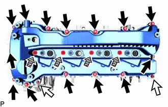
Remove the 14 bolts, 4 nozzle holder clamp seats, 2 nuts and cylinder head cover sub-assembly from the cylinder head sub-assembly.
Text in Illustration 
Bolt 
Nut 
Nozzle Holder Clamp Seat -
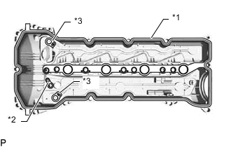
Text in Illustration *1 Cylinder Head Cover Gasket *2 No. 2 Cylinder Head Cover Gasket *3 Camshaft Bearing Cap Oil Hole Gasket Remove the cylinder head cover gasket, No. 2 cylinder head cover gasket and 2 camshaft bearing cap oil hole gaskets from the cylinder head cover sub-assembly.
-
-
REMOVE ENGINE OIL LEVEL SENSOR
-
REMOVE NO. 2 OIL PAN SUB-ASSEMBLY
-
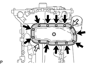
Remove the 2 nuts and 11 bolts.
Text in Illustration Bolt Nut -
Insert the blade of an oil pan seal cutter between the oil pan sub-assembly and No. 2 oil pan sub-assembly, cut off the applied sealer and remove the No. 2 oil pan sub-assembly.
Note
-
Be careful not to damage the contact surfaces of the oil pan sub-assembly and No. 2 oil pan sub-assembly.
-
Be careful not to damage the oil pan sub-assembly flange.
-
-
-
REMOVE OIL PAN SUB-ASSEMBLY
-
Remove the 2 nuts and 23 bolts.
Text in Illustration Bolt Nut -
Insert the blade of an oil pan seal cutter between the oil pan sub-assembly and cylinder block sub-assembly, cut off the applied sealer and remove the oil pan sub-assembly.
Note
-
Be careful not to damage the contact surfaces of the oil pan sub-assembly and cylinder block sub-assembly.
-
Be careful not to damage the cylinder block sub-assembly flange.
-
-
-
SET NO. 1 CYLINDER TO TDC/COMPRESSION
-
REMOVE ENGINE WATER PUMP ASSEMBLY
-
REMOVE TIMING CHAIN COVER PLATE
-
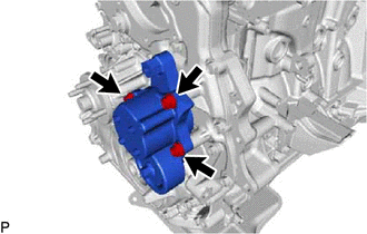
REMOVE SUPPLY PUMP ASSEMBLY
-
REMOVE INJECTION PUMP INSULATOR
-
REMOVE TIMING CHAIN COVER SUB-ASSEMBLY
-
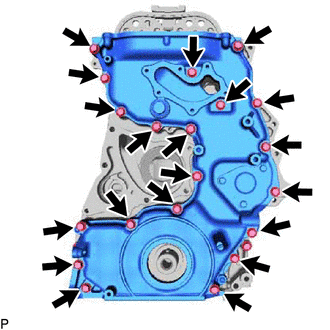
Remove the 20 bolts from the timing chain cover sub-assembly.
-
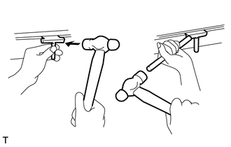
Using a screwdriver wrapped in protective tape, remove the timing chain cover sub-assembly by prying the points in the illustration.
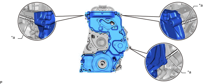
Text in Illustration *a Protective Tape - - Note
Do not damage the contacting surfaces of the timing chain cover sub-assembly and timing chain case assembly.
-
Remove the timing chain case gasket from the timing chain case assembly.
-
-
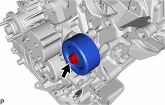
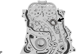
REMOVE FRONT CRANKSHAFT OIL SEAL
-
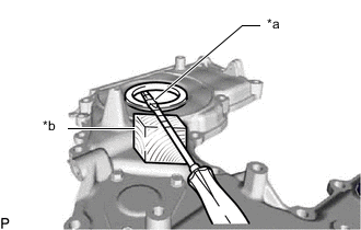
Text in Illustration *a Protective Tape *b Wooden Block Using a screwdriver and wooden block, pull out the front crankshaft oil seal.
Note
Do not damage the surface of the front crankshaft oil seal press fit hole.
-
-
INSPECT BACKLASH OF OIL PUMP GEAR TO OIL PUMP DRIVE GEAR
-
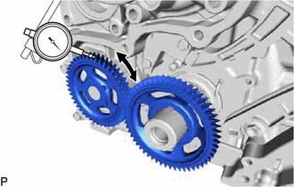
Using a dial indicator, measure the backlash.
Standard gear backlash 0.02 to 0.3 mm (0.000787 to 0.0118 in.) Maximum gear backlash 0.42 mm (0.0165 in.) If the gear backlash is more than the maximum, replace the timing chain case assembly or oil pump drive gear.
-
-
REMOVE OIL PUMP DRIVE GEAR
-
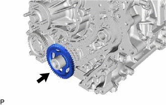
Remove the oil pump drive gear from the crankshaft.
-
-
REMOVE NO. 3 CHAIN TENSIONER ASSEMBLY
-
REMOVE NO.1 BALANCE SHAFT THRUST PLATE
-
REMOVE BALANCE SHAFT TIMING SPROCKET, BALANCE SHAFT GEAR SUB-ASSEMBLY AND NO. 3 CHAIN SUB-ASSEMBLY
-
REMOVE TIMING CHAIN GUIDE
-
REMOVE NO. 2 CHAIN TENSIONER ASSEMBLY
-
REMOVE NO. 2 CHAIN TENSIONER SLIPPER
-
REMOVE NO. 2 CHAIN VIBRATION DAMPER
-
REMOVE NO. 2 CHAIN SUB-ASSEMBLY
-
REMOVE NO. 1 CHAIN TENSIONER ASSEMBLY
-
REMOVE NO. 1 CHAIN TENSIONER SLIPPER
-
REMOVE NO. 1 CHAIN VIBRATION DAMPER
-
REMOVE CRANKSHAFT TIMING SPROCKET, INJECTION PUMP DRIVE GEAR WITH NO. 1 CHAIN SUB-ASSEMBLY
-
REMOVE CAMSHAFT TIMING SPROCKET
-
REMOVE TIMING CHAIN CASE ASSEMBLY
-
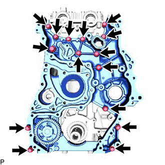
Remove the 15 bolts from the timing chain case assembly.
-
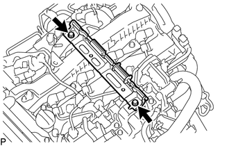
Using a screwdriver wrapped in protective tape, remove the timing chain case assembly by prying the points in the illustration.
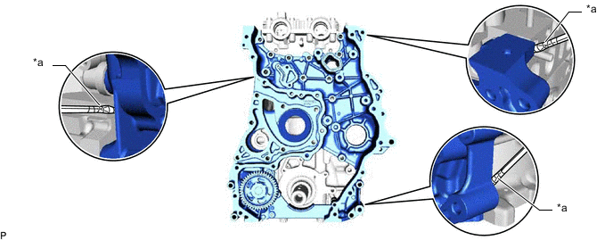
Text in Illustration *a Protective Tape - - Note
Do not damage the contacting surfaces of the timing chain case assembly, cylinder head sub-assembly and cylinder block sub-assembly.
-
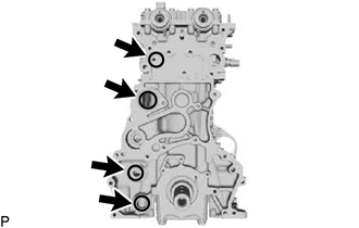
Remove the 4 O-rings from the cylinder head sub-assembly and cylinder block sub-assembly.
-