LIGHTING SYSTEM TERMINALS OF ECU

-
CHECK INSTRUMENT PANEL JUNCTION BLOCK ASSEMBLY AND MAIN BODY ECU (MULTIPLEX NETWORK BODY ECU)
-
Disconnect the instrument panel junction block assembly and main body ECU (multiplex network body ECU) connectors.
-
Measure the voltage on the wire harness side connector according to the value(s) in the table below.
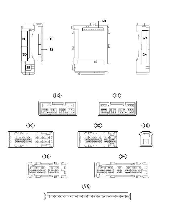
Terminal No. (Symbol) Wiring Color Terminal Description Condition Specified Condition 3D-31 - Body ground V - Body ground Auxiliary battery power supply Power switch off 11 to 14 V 3E-1 - Body ground W - Body ground Auxiliary battery power supply Power switch off 11 to 14 V If the result is not as specified, there may be a malfunction in the wire harness.
-
Measure the resistance on the wire harness side connector according to the value(s) in the table below.
Terminal No. (Symbol) Wiring Color Terminal Description Condition Specified Condition 3B-7 - Body ground W-B - Body ground Ground Always Below 1 Ω I12-3 (GND2) - Body ground W-B - Body ground Ground Always Below 1 Ω If the result is not as specified, there may be a malfunction in the wire harness.
-
Reconnect the instrument panel junction block assembly and main body ECU (multiplex network body ECU) connectors.
-
Measure the voltage and check for pulses according to the value(s) in the table below.
Terminal No. (Symbol) Wiring Color Terminal Description Condition Specified Condition 3D-3 - Body ground GR - Body ground Front side marker light LH drive output Light control switch in tail or head position 11 to 14 V Light control switch off Below 1 V 3D-6 - Body ground B - Body ground Front side marker light RH drive output Light control switch in tail or head position 11 to 14 V Light control switch off Below 1 V 3D-7 - Body ground L - Body ground Parking light RH drive output Light control switch in tail or head position 11 to 14 V Light control switch off Below 1 V 3D-8 - Body ground W - Body ground Parking light LH drive output Light control switch in tail or head position 11 to 14 V Light control switch off Below 1 V 3D-9 - Body ground P - Body ground TAIL relay drive signal output Light control switch in tail or head position 11 to 14 V Light control switch off Below 1 V 3D-12 - Body ground P - Body ground Headlight relay drive output Light control switch in head position Below 1 V Light control switch not in head position 11 to 14 V 3D-20 - Body ground Y - Body ground Parking brake switch input Parking brake switch on Below 1 V Parking brake switch off 11 to 14 V 3D-23 - Body ground BR - Body ground*1
P - Body ground*2
Daytime running light system drive output Daytime running light system operating Below 1 V Daytime running light system not operating 11 to 14 V 3D-39 - Body ground W - Body ground High beam headlight drive output Dimmer switch in high or high flash position Below 1 V Dimmer switch in low position 11 to 14 V 3C-5 - Body ground P - Body ground Taillight relay drive signal output Light control switch in tail or head position 11 to 14 V Light control switch off Below 1 V I12-21 (RLEW) - Body ground*3 BE - Body ground Light control ECU RH signal input Power switch on (IG), light control switch off 11 to 14 V Power switch on (IG), light control switch in head position Pulse generation I12-24 (LLEW) - Body ground*3 SB - Body ground Light control ECU LH signal input Power switch on (IG), light control switch off 11 to 14 V Power switch on (IG), light control switch in head position Pulse generation I13-5 (HU) - Body ground LG - Body ground Dimmer switch high position signal input Dimmer switch in high position Below 1 V Dimmer switch not in high position Pulse generation I13-8 (HF) - Body ground R - Body ground Dimmer switch high flash position signal input Dimmer switch in high flash position Below 1 V Dimmer switch not in high flash position Pulse generation I13-20 (CLTB) - I13-22 (CLTE) B - P Automatic light control sensor power supply output Power switch off Below 1 V Power switch on (IG), light control switch in AUTO position 11 to 14 V I13-21 (CLTS) - Body ground G - Body ground Automatic light control sensor signal input Power switch off Below 1 V Automatic light control system operates Pulse generation
(See waveform 1)
I13-28 (A) - Body ground G - Body ground Light control switch AUTO position signal input Light control switch in AUTO position Below 1 V Light control switch not in AUTO position Pulse generation I13-29 (HEAD) - Body ground P - Body ground Light control switch head position input Light control switch in head position Below 1 V Light control switch not in head position, power switch off Pulse generation Light control switch not in head position, power switch on (IG) 11 to 14 V I13-30 (TAIL) - Body ground B - Body ground Light control switch tail position signal input Light control switch in tail or head position Below 1 V Light control switch in neither tail nor head position, power switch off Pulse generation Light control switch in neither tail nor head position, power switch on (IG) 11 to 14 V
-
*1: for DRL LED Type
-
*2: except DRL LED Type
-
*3: for LED Headlight
If the result is not as specified, the main body ECU (multiplex network body ECU) or instrument panel junction block assembly may have a malfunction.
-
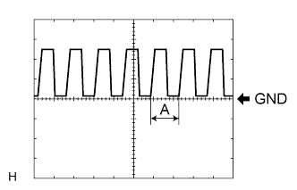
Waveform 1
Item Content Tool setting 5 V/DIV., 5 ms./DIV. Tech Tips
If the ambient light becomes brighter, width (A) becomes narrower.
-
-
-
CHECK POWER MANAGEMENT CONTROL ECU
-
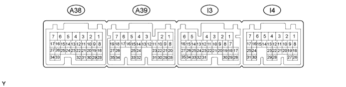
Disconnect the I3 power management control ECU connector.
-
Measure the voltage according to the value(s) in the table below.
Terminal No. (Symbol) Wiring Color Terminal Description Condition Specified Condition I3-8 (BL) - Body ground W - Body ground Back-up light signal Power switch on (IG), shift lever not in R Below 1 V Power switch on (IG), shift lever in R 11 to 14 V If the result is not as specified, there may be a malfunction in the wire harness.
-