OUTER REAR VIEW MIRROR DISASSEMBLY

Tech Tips
-
Use the same procedure for the RH side and LH side.
-
The following procedure is for the LH side.
-
REMOVE OUTER MIRROR (w/o Side Turn Signal Light)
-
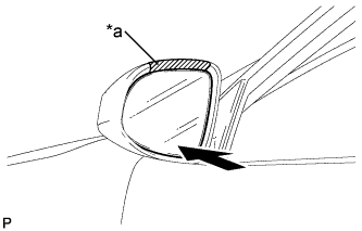
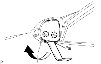
Text in Illustration *a Protective Tape Apply protective tape to the areas shown in the illustration.
-
Push the lower part of the mirror surface and tilt it.
-
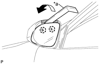
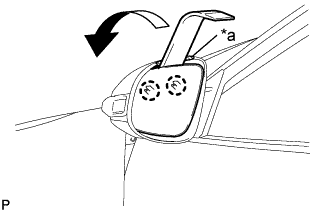
Text in Illustration *a Moulding Remover Using a moulding remover, disengage the 2 claws at the upper part of the outer mirror as shown in the illustration.
-
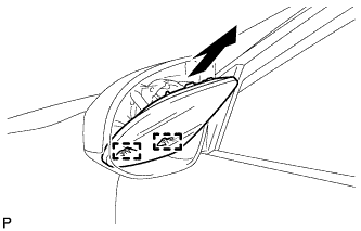
Disengage the 2 guides and remove the outer mirror as shown in the illustration.
-
w/o Blind Spot Monitor System:
-
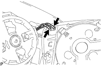
Disconnect the 2 connectors and remove the outer mirror.
-
-
w/ Blind Spot Monitor System:
-
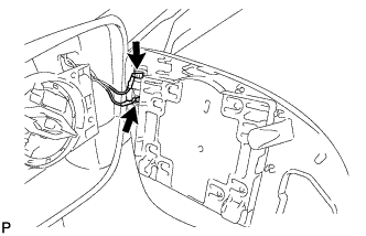
Disconnect the 2 mirror heater connectors.
-
Disengage the 2 claws.
-
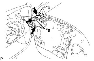
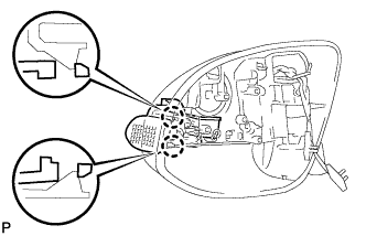
Text in Illustration *a Mirror Heater Connector *b Blind Spot Monitor Indicator Connector Using a screwdriver, release the tabs of the blind spot monitor indicator connector to disconnect the connector and remove the outer mirror.
Note
-
Do not bend the tabs excessively to prevent them from being damaged.
-
If the tabs are damaged, replace the outer mirror with a new one.
-
-
-
-
REMOVE OUTER MIRROR (w/ Side Turn Signal Light)
-
Text in Illustration *a Protective Tape Apply protective tape to the area shown in the illustration.
-
Push the upper part of the mirror surface and tilt it.
-
Using a moulding remover, disengage the 2 claws at the lower part of the outer mirror as shown in the illustration.
-
Text in Illustration *a Protective Tape Apply protective tape to the area shown in the illustration.
-
Push the lower part of the mirror surface and tilt it.
-
Using a moulding remover, disengage the 2 claws at the upper part of the outer mirror as shown in the illustration.
-
Disconnect the 2 connectors and remove the outer mirror.
-
-
REMOVE OUTER MIRROR COVER (w/o Side Turn Signal Light)
-
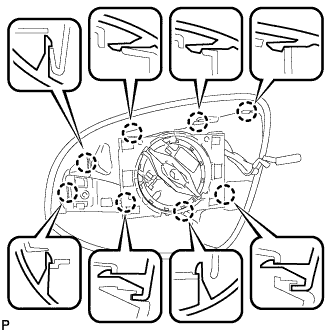
Disengage the 8 claws and remove the outer mirror cover.
-
-
REMOVE OUTER MIRROR COVER (w/ Side Turn Signal Light)
-
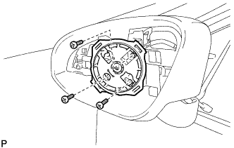
Remove the 3 screws.
-
Disengage the clamp.
-
Disconnect the connector and remove the mirror actuator.
-
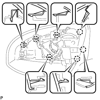
Disengage the 7 claws and remove the outer mirror cover.
-
-
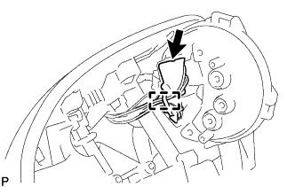
REMOVE SIDE TURN SIGNAL LIGHT ASSEMBLY (w/ Side Turn Signal Light)
-
Disengage the 2 claws.
-
Disconnect the connector and remove the side turn signal light assembly.
-