WINDSHIELD GLASS REMOVAL

Note
When replacing the windshield glass of a vehicle equipped with a lane departure warning camera, make sure to use a Toyota genuine part. If a non-Toyota genuine part is used, the lane departure warning camera may not be able to be installed due to a missing bracket or the lane departure alert system may not operate properly due to a difference in the transmissivity or black ceramic border.
-
REMOVE FRONT WIPER ARM AND BLADE ASSEMBLY LH
-
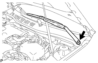
Remove the nut and front wiper arm and blade assembly LH.
-
-
REMOVE FRONT WIPER ARM AND BLADE ASSEMBLY RH
-
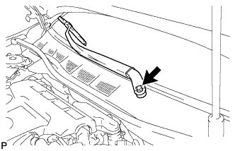
Remove the nut and front wiper arm and blade assembly RH.
-
-
REMOVE FRONT FENDER TO COWL SIDE SEAL LH
-
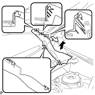
Disengage the 2 clips and 3 guides, and remove the front fender to cowl side seal LH as shown in the illustration.
-
-
REMOVE FRONT FENDER TO COWL SIDE SEAL RH
Tech Tips
Use the same procedure as for the LH side.
-
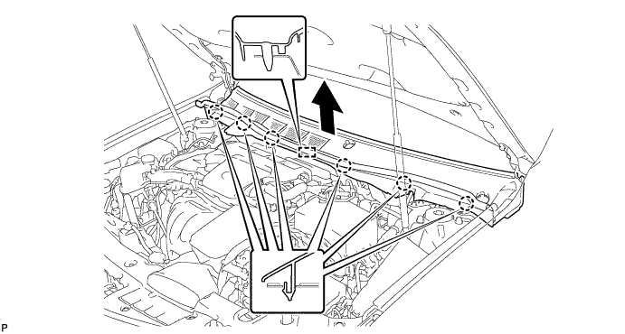
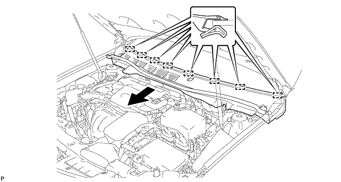
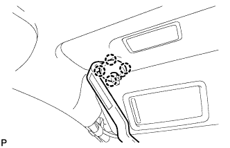
REMOVE COWL TOP VENTILATOR LOUVER SUB-ASSEMBLY
-
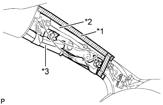
Disengage the 6 claws and guide as shown in the illustration.
-
Disengage the 8 guides and pull out the cowl top ventilator louver sub-assembly as shown in the illustration.
-
-
REMOVE HUMIDITY SENSOR (AIR CONDITIONING THERMISTOR ASSEMBLY)
-
REMOVE INNER REAR VIEW MIRROR ASSEMBLY
-
REMOVE LANE DEPARTURE WARNING CAMERA (w/ Lane Departure Alert System)
-
DISCONNECT FRONT DOOR OPENING TRIM WEATHERSTRIP LH
-
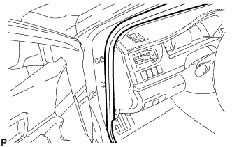
Disconnect the front door opening trim weatherstrip LH.
-
-
REMOVE FRONT PILLAR GARNISH LH
-
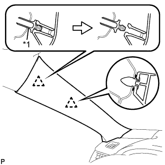
Text in Illustration *1 Front Pillar Garnish Clip Pull the upper part of the garnish toward the inside of the cabin and disengage the garnish from the base of the 2 clips.
Tech Tips
Make the front pillar garnish LH hang down from the front pillar garnish clip.
-
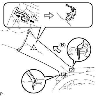
While pushing the tabs on the front pillar garnish clip in the direction indicated by the arrow (A) shown in the illustration, disengage the front pillar garnish clip.
Note
Do not apply excessive force using a tool.
-
Pull the garnish in the direction indicated by the arrow (B) shown in the illustration to disengage the 2 guides and remove the front pillar garnish LH.
-
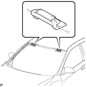
Text in Illustration *1 Adhesive Tape *2 Protective Cover *3 Curtain Shield Airbag Assembly Protect the curtain shield airbag assembly.
-
Cover the airbag with a piece of cloth or nylon and secure the edges of the cover with tape as shown in the illustration.
Note
Cover the curtain shield airbag with a protective cover as soon as the front pillar garnish is removed.
-
-
-
DISCONNECT FRONT DOOR OPENING TRIM WEATHERSTRIP RH
Tech Tips
Use the same procedure as for the LH side.
-
REMOVE FRONT PILLAR GARNISH RH
Tech Tips
Use the same procedure as for the LH side.
-
REMOVE ROOF CONSOLE BOX ASSEMBLY (w/o Sliding Roof)
-
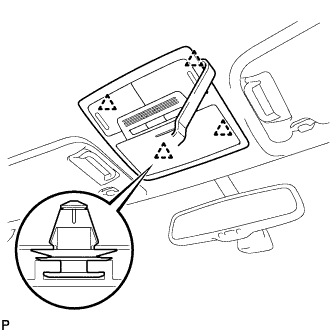
Using a moulding remover, disengage the 4 clips.
-
Disconnect the connector and remove the roof console box assembly.
-
-
REMOVE ROOF CONSOLE BOX ASSEMBLY (w/ Sliding Roof)
-
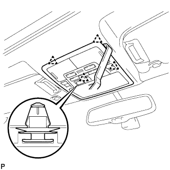
Using a moulding remover, disengage the 4 clips.
-
Disconnect the connector and remove the roof console box assembly.
-
-
REMOVE NO. 1 ROOM LIGHT ASSEMBLY (w/o Sliding Roof)
-
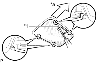
Text in Illustration *1 Protective Tape *a Front Using a screwdriver with its tip wrapped with protective tape, disengage the 4 claws and remove the No. 1 room light lens.
-
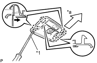
Text in Illustration *1 Protective Tape *a Front Using a screwdriver with its tip wrapped with protective tape, disengage the 4 claws as shown in the illustration and remove the No. 1 room light housing.
-
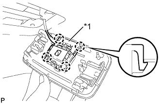
Text in Illustration *1 Room Light Switch Base Using a screwdriver, disengage the 4 claws and disconnect the room light switch base from the No. 1 room light housing.
-
-
REMOVE SPOT LIGHT ASSEMBLY (w/ Sliding Roof)
-
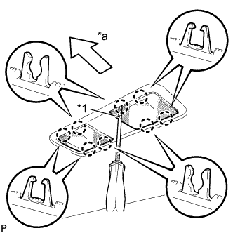
Text in Illustration *1 Protective Tape *a Front Using a screwdriver with its tip wrapped with protective tape, disengage the 8 claws and remove the 2 spot light lenses.
-
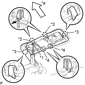
Text in Illustration *1 Protective Tape *2 Claw <A> *3 Claw <B> *4 Claw <C> *a Front Using a screwdriver with its tip wrapped with protective tape and moulding remover, disengage the 2 claws <A>.
-
Disengage the 2 claws <B> and 2 claws <C>, and disconnect the spot light housing.
-
Text in Illustration *1 Map Light Sub-assembly Using a screwdriver, disengage the 8 claws and disconnect the 2 map light sub-assemblies from the spot light housing.
-
-
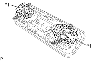
REMOVE ASSIST GRIP SUB-ASSEMBLY
-
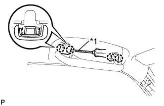
Text in Illustration *1 Protective Tape Using a screwdriver, disengage the 4 claws and remove the 2 assist grip covers.
Note
Do not forcibly pry the assist grip covers to prevent them from being deformed.
Tech Tips
Tape the screwdriver tip before use.
-
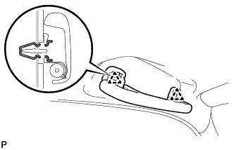
Disengage the 2 clips and remove the assist grip sub-assembly.
-
Remove the 2 clips from the vehicle body.
Tech Tips
Use the same procedure for the RH side.
-
-
REMOVE REAR ASSIST GRIP ASSEMBLY LH
-

Text in Illustration *1 Protective Tape Using a screwdriver, disengage the 4 claws and remove the 2 assist grip covers.
Note
Do not forcibly pry the assist grip covers to prevent them from being deformed.
Tech Tips
Tape the screwdriver tip before use.
-
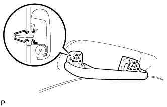
Disengage the 2 clips and remove the rear assist grip assembly LH.
-
Remove the 2 clips from the vehicle body.
-
-
REMOVE REAR ASSIST GRIP ASSEMBLY RH
Tech Tips
Use the same procedure as for the LH side.
-
REMOVE SLIDING ROOF OPENING TRIM MOULDING (w/ Sliding Roof)
-
Remove the sliding roof opening trim moulding.
-
-
REMOVE VISOR BRACKET COVER (for LH Side)
-
Using a moulding remover, disengage the 4 claws and remove the visor bracket cover.
-
-
REMOVE VISOR ASSEMBLY LH
-
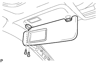
Remove the 2 screws and visor assembly LH.
-
-
REMOVE VISOR BRACKET COVER (for RH Side)
Tech Tips
Use the same procedure as for the LH side.
-
REMOVE VISOR ASSEMBLY RH
Tech Tips
Use the same procedure as for the LH side.
-
REMOVE VISOR HOLDER
-
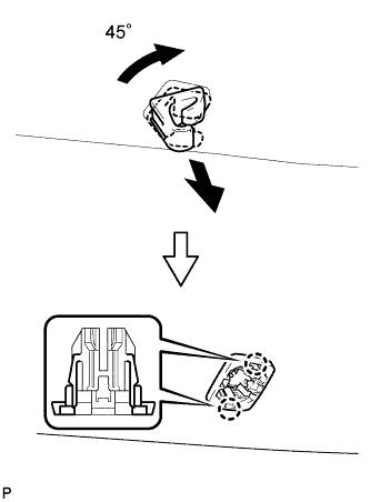
Turn the visor holder approximately 45° and pull it out as shown in the illustration.
-
Disengage the 2 claws and remove the visor holder.
Tech Tips
Use the same procedure for the other visor holder.
-
-
REMOVE ROOF HEADLINING ASSEMBLY
-
Slightly lower the front section of the roof headlining assembly so that the windshield glass can be removed.
Note
Do not damage the roof headlining assembly or vehicle interior.
Tech Tips
It is not necessary to completely remove the roof headlining assembly.
-
-
REMOVE WINDSHIELD GLASS SUB-ASSEMBLY
-
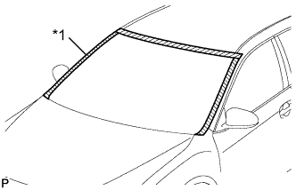
Text in Illustration *1 Protective Tape Apply protective tape to the area around the installation position of the windshield glass sub-assembly on the vehicle body to prevent it from being scratched.
-
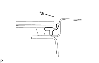
Text in Illustration *a Cut Off Using a knife, cut off the windshield outside moulding as shown in the illustration.
-
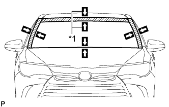
Text in Illustration *1 Matchmark Place matchmarks on the windshield glass sub-assembly and vehicle body at the locations indicated in the illustration.
Tech Tips
Matchmarks are not necessary if the windshield glass sub-assembly is not going to be reused.
-
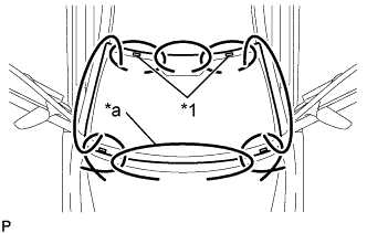
Text in Illustration *1 Windshield Glass Stopper *a Piano Wire Pass a piano wire between the vehicle body and windshield glass sub-assembly from the interior.
-
Tie both wire ends to wooden blocks or similar objects that can serve as handles.
-
Cut off the adhesive by pulling the piano wire around the windshield glass sub-assembly.
Note
-
When removing the windshield glass sub-assembly, be careful not to damage the paint or interior and exterior ornaments.
-
To prevent the safety pad from being scratched when removing the windshield glass sub-assembly, place a plastic sheet between the piano wire and safety pad.
-
-
Disengage the windshield glass stoppers and windshield glass retainers.
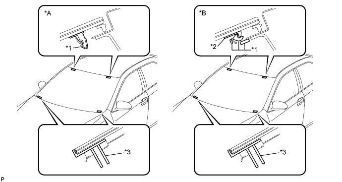
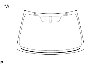
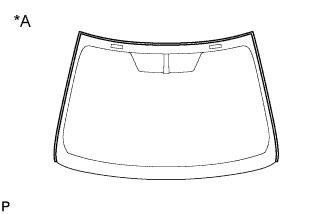
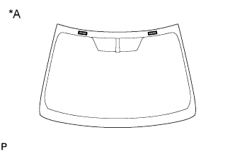
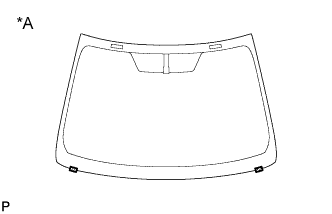
Text in Illustration *A for 1-piece Type *B for 2-piece Type *1 No. 1 Windshield Glass Stopper *2 No. 2 Windshield Glass Stopper *3 Windshield Glass Retainer - - Note
-
The No. 1 windshield glass stoppers, No. 2 windshield glass stoppers and windshield glass retainers are installed to the windshield glass as shown in the illustration. Be careful not to damage the windshield glass sub-assembly when cutting off the adhesive.
-
To prevent the windshield glass sub-assembly from falling when performing this operation, be sure to hold the windshield glass sub-assembly using suction cups.
Tech Tips
Depending on the vehicle, either 1-piece type or 2-piece type stoppers may be present.
-
-
Using suction cups, remove the windshield glass sub-assembly.
Note
-
Be careful not to drop the windshield glass sub-assembly.
-
Leave as much adhesive on the vehicle body as possible when removing the windshield glass sub-assembly.
-
-
-
REMOVE WINDSHIELD GLASS ADHESIVE DAM
-
When reusing the windshield glass:
-
Text in Illustration *A Back Side Using a scraper, remove the windshield glass adhesive dam from the back side of the windshield glass.
Note
-
Be careful not to damage the windshield glass.
-
Be sure to replace the window glass adhesive dam with a new one.
-
-
-
-
REMOVE WINDSHIELD OUTSIDE MOULDING
-
When reusing the windshield glass:
-
Text in Illustration *A Back Side Using a scraper, remove the windshield outside moulding from the back side of the windshield glass.
Note
-
Be careful not to damage the windshield glass.
-
Be sure to replace the windshield outside moulding with a new one.
-
-
-
-
REMOVE NO. 1 WINDSHIELD GLASS STOPPER (for 1-piece Type)
-
When reusing the windshield glass:
-
Text in Illustration *A Back Side Using a scraper, remove the 2 No. 1 windshield glass stoppers from the back side of the windshield glass.
Note
-
Be careful not to damage the windshield glass.
-
Be sure to replace the 1-piece type No. 1 windshield glass stoppers with new 2-piece type No. 1 and No. 2 windshield glass stoppers.
-
-
-
-
REMOVE NO. 2 WINDSHIELD GLASS STOPPER (for 2-piece Type)
-
When reusing the windshield glass:
-
Text in Illustration *A Back Side Using a scraper, remove the 2 No. 2 windshield glass stoppers from the back side of the windshield glass.
Note
-
Be careful not to damage the windshield glass.
-
Be sure to replace the No. 2 windshield glass stoppers with new ones.
-
-
-
-
REMOVE WINDSHIELD GLASS RETAINER
-
When reusing the windshield glass:
-
Text in Illustration *A Back Side Remove the 2 windshield glass retainers from the back side of the windshield glass.
Note
-
Be careful not to damage the windshield glass.
-
Be sure to replace the windshield glass retainers with new ones.
-
-
-
-
REMOVE NO. 1 WINDSHIELD GLASS STOPPER (for 2-piece Type)
-
Remove the 2 No. 1 windshield glass stoppers.
Note
Be sure to replace the No. 1 windshield glass stoppers with new ones.
-
-
CLEAN WINDSHIELD GLASS
-
When reusing the windshield glass:
-
Using a scraper, remove any remaining adhesive dam and adhesive residue from the windshield glass.
Note
Be careful not to damage the windshield glass.
-
Clean the outer circumference of the windshield glass with a non-residue solvent.
Note
-
Do not touch the windshield glass surface after cleaning it.
-
Even if using a new windshield glass, clean it with a non-residue solvent.
-
-
-
-
CLEAN VEHICLE BODY
-
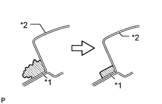
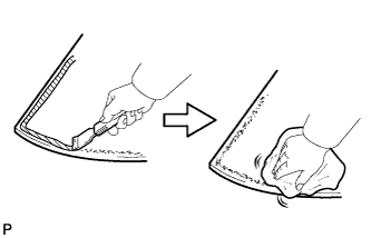
Text in Illustration *1 Adhesive *2 Vehicle Body Clean and shape the contact surface of the vehicle body.
-
Using a knife, cut away excess adhesive on the contact surface of the vehicle body as shown in the illustration.
Note
Be careful not to damage the vehicle body.
Tech Tips
Leave as much adhesive on the vehicle body as possible.
-
Clean the contact surface of the vehicle body with a piece of cloth saturated with non-residue solvent.
Tech Tips
Even if all of the adhesive has been removed, clean the vehicle body.
-
-