POWER WINDOW CONTROL SYSTEM TERMINALS OF ECU

-
CHECK POWER WINDOW REGULATOR MASTER SWITCH ASSEMBLY

-
Disconnect the K11 power window regulator master switch assembly connector.
-
Measure the voltage and resistance according to the value(s) in the table below.
Tech Tips
Measure the values on the wire harness side with the connector disconnected.
Terminal No. (Symbol) Wiring Color Terminal Description Condition Specified Condition K11-3 (B) - K11-1 (GND) R - W-B Power supply Always 11 to 14 V K11-13 (PWS) - K11-1 (GND) LG - W-B Power supply Power switch on (IG) 11 to 14 V K11-1 (GND) - Body ground W-B - Body ground Ground Always Below 1 Ω -
Reconnect the K11 power window regulator master switch assembly connector.
-
Measure the voltage according to the value(s) in the table below.
Terminal No. (Symbol) Wiring Color Terminal Description Condition Specified Condition K11-5 (DOWN) - K11-1 (GND) V - W-B Power window motor down output Power switch on (IG), driver door power window regulator switch not pushed or pulled 11 to 14 V K11-5 (DOWN) - K11-1 (GND) V - W-B Power window motor down output Power switch on (IG), driver door power window moving, driver door power window regulator switch pushed halfway down (Manual operation) Below 1 V K11-4 (UP) - K11-1 (GND) L - W-B Power window motor up output Power switch on (IG), driver door power window regulator switch not pushed or pulled 11 to 14 V K11-4 (UP) - K11-1 (GND) L - W-B Power window motor up output Power switch on (IG), driver door power window moving, driver door power window regulator switch pulled halfway up (Manual operation) Below 1 V K11-12 (RLU) - K11-1 (GND) L - W-B Power window motor up output Power switch on (IG), rear LH door power window regulator switch off Below 1 V K11-12 (RLU) - K11-1 (GND) L - W-B Power window motor up output Power switch on (IG), rear LH door power window regulator switch up (Manual operation) 11 to 14 V K11-15 (RLD) - K11-1 (GND) B - W-B Power window motor down output Power switch on (IG), rear LH door power window regulator switch off Below 1 V K11-15 (RLD) - K11-1 (GND) B - W-B Power window motor down output Power switch on (IG), rear LH door power window regulator switch down (Manual operation) 11 to 14 V K11-10 (RRU) - K11-1 (GND) Y - W-B Power window motor up output Power switch on (IG), rear RH door power window regulator switch off Below 1 V K11-10 (RRU) - K11-1 (GND) Y - W-B Power window motor up output Power switch on (IG), rear RH door power window regulator switch up (Manual operation) 11 to 14 V K11-16 (RRD) - K11-1 (GND) LG - W-B Power window motor down output Power switch on (IG), rear RH door power window regulator switch off Below 1 V K11-16 (RRD) - K11-1 (GND) LG - W-B Power window motor down output Power switch on (IG), rear RH door power window regulator switch down (Manual operation) 11 to 14 V
-
-
CHECK POWER WINDOW REGULATOR SWITCH ASSEMBLY

-
Disconnect the J11 power window regulator switch assembly connector.
-
Measure the resistance according to the value(s) in the table below.
Tech Tips
Measure the values on the wire harness side with the connector disconnected.
Terminal No. (Symbol) Wiring Color Terminal Description Condition Specified Condition J11-7 (GND) - Body ground W-B - Body ground Ground Always Below 1 Ω -
Reconnect the J11 power window regulator switch assembly connector.
-
Measure the voltage according to the value(s) in the table below.
Terminal No. (Symbol) Wiring Color Terminal Description Condition Specified Condition J11-2 (IG) - J11-7 (GND) R - W-B IG power supply Power switch on (IG) 11 to 14 V J11-2 (IG) - J11-7 (GND) R - W-B IG power supply Power switch off Below 1 V J11-5 (UP) - J11-7 (GND) L - W-B Power window motor up output Power switch on (IG), power window regulator switch assembly not pushed or pulled 11 to 14 V J11-5 (UP) - J11-7 (GND) L - W-B Power window motor up output Power switch on (IG), front passenger door power window moving, power window regulator switch assembly pulled halfway up (Manual operation) Below 1 V J11-5 (UP) - J11-7 (GND) L - W-B Power window motor up output Power switch on (IG), front passenger door power window fully open 11 to 14 V J11-5 (UP) - J11-7 (GND) L - W-B Power window motor up output Power switch on (IG), front passenger door power window moving, power window regulator switch assembly fully pulled up (Auto operation) Below 1 V J11-5 (UP) - J11-7 (GND) L - W-B Power window motor up output Power switch on (IG), front passenger door power window fully closed 11 to 14 V J11-4 (DOWN) - J11-7 (GND) V - W-B Power window motor down output Power switch on (IG), power window regulator switch assembly not pushed or pulled 11 to 14 V J11-4 (DOWN) - J11-7 (GND) V - W-B Power window motor down output Power switch on (IG), front passenger door power window moving, power window regulator switch assembly pushed halfway down (Manual operation) Below 1 V J11-4 (DOWN) - J11-7 (GND) V - W-B Power window motor down output Power switch on (IG), front passenger door power window fully closed 11 to 14 V J11-4 (DOWN) - J11-7 (GND) V - W-B Power window motor down output Power switch on (IG), front passenger door power window moving, power window regulator switch assembly fully pushed down (Auto operation) Below 1 V J11-4 (DOWN) - J11-7 (GND) V - W-B Power window motor down output Power switch on (IG), front passenger door power window fully open 11 to 14 V J11-8 (AUTO) - J11-7 (GND) Y - W-B Power window motor auto up output Power switch on (IG), front passenger door power window fully open 11 to 14 V J11-8 (AUTO) - J11-7 (GND) Y - W-B Power window motor auto up output Power switch on (IG), front passenger door power window moving, power window regulator switch assembly fully pulled up (Auto operation) Below 1 V J11-8 (AUTO) - J11-7 (GND) Y - W-B Power window motor auto up output Power switch on (IG), front passenger door power window fully closed 11 to 14 V J11-8 (AUTO) - J11-7 (GND) Y - W-B Power window motor auto down output Power switch on (IG), front passenger door power window fully closed 11 to 14 V J11-8 (AUTO) - J11-7 (GND) Y - W-B Power window motor auto down output Power switch on (IG), front passenger door power window moving, power window regulator switch assembly fully pushed down (Auto operation) Below 1 V J11-8 (AUTO) - J11-7 (GND) Y - W-B Power window motor auto down output Power switch on (IG), front passenger door power window fully open 11 to 14 V
-
-
CHECK REAR POWER WINDOW REGULATOR SWITCH ASSEMBLY (FOR LH DOOR)

-
Disconnect the M6 rear power window regulator switch assembly (for LH door) connector.
-
Measure the voltage according to the value(s) in the table below.
Tech Tips
Measure the values on the wire harness side with the connector disconnected.
Terminal No. (Symbol) Wiring Color Terminal Description Condition Specified Condition M6-2 (B) - Body ground G - Body ground Power supply Power switch on (IG) 11 to 14 V -
Reconnect the M6 rear power window regulator switch assembly (for LH door) connector.
-
Measure the voltage according to the value(s) in the table below.
Terminal No. (Symbol) Wiring Color Terminal Description Condition Specified Condition M6-7 (U) - Body ground B - Body ground Power window motor up output Power switch on (IG), rear power window regulator switch assembly (for LH door) off Below 1 V M6-7 (U) - Body ground B - Body ground Power window motor up output Power switch on (IG), rear power window regulator switch assembly (for LH door) up (Manual operation) 11 to 14 V M6-1 (D) - Body ground R - Body ground Power window motor down output Power switch on (IG), rear power window regulator switch assembly (for LH door) off Below 1 V M6-1 (D) - Body ground R - Body ground Power window motor down output Power switch on (IG), rear power window regulator switch assembly (for LH door) down (Manual operation) 11 to 14 V
-
-
CHECK REAR POWER WINDOW REGULATOR SWITCH ASSEMBLY (FOR RH DOOR)

-
Disconnect the L6 rear power window regulator switch assembly (for RH door) connector.
-
Measure the voltage according to the value(s) in the table below.
Tech Tips
Measure the values on the wire harness side with the connector disconnected.
Terminal No. (Symbol) Wiring Color Terminal Description Condition Specified Condition L6-2 (B) - Body ground G - Body ground Power supply Power switch on (IG) 11 to 14 V -
Reconnect the L6 rear power window regulator switch assembly (for RH door) connector.
-
Measure the voltage according to the value(s) in the table below.
Terminal No. (Symbol) Wiring Color Terminal Description Condition Specified Condition L6-7 (U) - Body ground B - Body ground Power window motor up output Power switch on (IG), rear power window regulator switch assembly (for RH door) off Below 1 V L6-7 (U) - Body ground B - Body ground Power window motor up output Power switch on (IG), rear power window regulator switch assembly (for RH door) up (Manual operation) 11 to 14 V L6-1 (D) - Body ground R - Body ground Power window motor down output Power switch on (IG), rear power window regulator switch assembly (for RH door) off Below 1 V L6-1 (D) - Body ground R - Body ground Power window motor down output Power switch on (IG), rear power window regulator switch assembly (for RH door) down (Manual operation) 11 to 14 V
-
-
CHECK POWER WINDOW REGULATOR MOTOR ASSEMBLY (FOR DRIVER DOOR)

-
Disconnect the K9 power window regulator motor assembly (for driver door) connector.
-
Measure the voltage and resistance according to the value(s) in the table below.
Tech Tips
Measure the values on the wire harness side with the connector disconnected.
Terminal No. (Symbol) Wiring Color Terminal Description Condition Specified Condition K9-1 (GND) - Body ground W-B - Body ground Ground Always Below 1 Ω K9-2 (B) - Body ground W - Body ground Power supply Always 11 to 14 V -
Reconnect the K9 power window regulator motor assembly (for driver door) connector.
-
Measure the voltage according to the value(s) in the table below.
Terminal No. (Symbol) Wiring Color Terminal Description Condition Specified Condition K9-7 (DOWN) - K9-1 (GND) V - W-B Power window motor down input Power switch on (IG), power window regulator master switch assembly (driver door power window regulator switch) not pushed or pulled 11 to 14 V K9-7 (DOWN) - K9-1 (GND) V - W-B Power window motor down input Power switch on (IG), driver door power window moving, power window regulator master switch assembly (driver door power window regulator switch) pushed halfway down (Manual operation) Below 1 V K9-7 (DOWN) - K9-1 (GND) V - W-B Power window motor down input Power switch on (IG), driver door power window fully closed 11 to 14 V K9-7 (DOWN) - K9-1 (GND) V - W-B Power window motor down input Power switch on (IG), driver door power window moving, power window regulator master switch assembly (driver door power window regulator switch) fully pushed down (Auto operation) Below 1 V K9-7 (DOWN) - K9-1 (GND) V - W-B Power window motor down input Power switch on (IG), driver door power window fully open 11 to 14 V K9-10 (UP) - K9-1 (GND) L - W-B Power window motor up input Power switch on (IG), power window regulator master switch assembly (driver door power window regulator switch) not pushed or pulled 11 to 14 V K9-10 (UP) - K9-1 (GND) L - W-B Power window motor up input Power switch on (IG), driver door power window moving, power window regulator master switch assembly (driver door power window regulator switch) pulled halfway up (Manual operation) Below 1 V K9-10 (UP) - K9-1 (GND) L - W-B Power window motor up input Power switch on (IG), power window regulator master switch assembly (driver door power window regulator switch) fully open 11 to 14 V K9-10 (UP) - K9-1 (GND) L - W-B Power window motor up input Power switch on (IG), driver door power window moving, power window regulator master switch assembly (driver door power window regulator switch) fully pulled up (Auto operation) Below 1 V K9-10 (UP) - K9-1 (GND) L - W-B Power window motor up input Power switch on (IG), driver door power window fully closed 11 to 14 V
-
-
CHECK POWER WINDOW REGULATOR MOTOR ASSEMBLY (FOR FRONT PASSENGER DOOR)

-
Disconnect the J14 power window regulator motor assembly (for front passenger door) connector.
-
Measure the voltage and resistance according to the value(s) in the table below.
Tech Tips
Measure the values on the wire harness side with the connector disconnected.
Terminal No. (Symbol) Wiring Color Terminal Description Condition Specified Condition J14-1 (GND) - Body ground W-B - Body ground Ground Always Below 1 Ω J14-2 (B) - Body ground GR - Body ground Power supply Always 11 to 14 V -
Reconnect the J14 power window regulator motor assembly (for front passenger door) connector.
-
Measure the voltage according to the value(s) in the table below.
Terminal No. (Symbol) Wiring Color Terminal Description Condition Specified Condition J14-5 (IG) - J14-1 (GND) R - W-B IG power supply Power switch on (IG) 11 to 14 V J14-5 (IG) - J14-1 (GND) R - W-B IG power supply Power switch off Below 1 V J14-4 (AUTO) - J14-1 (GND) Y - W-B Power window motor auto up input Power switch on (IG), front passenger door power window fully open 11 to 14 V J14-4 (AUTO) - J14-1 (GND) Y - W-B Power window motor auto up input Power switch on (IG), front passenger door power window moving, power window regulator switch assembly fully pulled up (Auto operation) Below 1 V J14-4 (AUTO) - J14-1 (GND) Y - W-B Power window motor auto up input Power switch on (IG), front passenger door power window fully closed 11 to 14 V J14-4 (AUTO) - J14-1 (GND) Y - W-B Power window motor auto down input Power switch on (IG), front passenger door power window fully closed 11 to 14 V J14-4 (AUTO) - J14-1 (GND) Y - W-B Power window motor auto down input Power switch on (IG), front passenger door power window moving, power window regulator switch assembly fully pushed down (Auto operation) Below 1 V J14-4 (AUTO) - J14-1 (GND) Y - W-B Power window motor auto down input Power switch on (IG), front passenger door power window fully open 11 to 14 V J14-7 (DOWN) - J14-1 (GND) V - W-B Power window motor down input Power switch on (IG), power window regulator switch assembly not pushed or pulled 11 to 14 V J14-7 (DOWN) - J14-1 (GND) V - W-B Power window motor down input Power switch on (IG), front passenger door power window moving, power window regulator switch assembly pushed halfway down (Manual operation) Below 1 V J14-7 (DOWN) - J14-1 (GND) V - W-B Power window motor down input Power switch on (IG), front passenger door power window fully closed 11 to 14 V J14-7 (DOWN) - J14-1 (GND) V - W-B Power window motor down input Power switch on (IG), front passenger door power window moving, power window regulator switch assembly fully pushed down (Auto operation) Below 1 V J14-7 (DOWN) - J14-1 (GND) V - W-B Power window motor down input Power switch on (IG), front passenger door power window fully open 11 to 14 V J14-10 (UP) - J14-1 (GND) L - W-B Power window motor up input Power switch on (IG), power window regulator switch assembly not pushed or pulled 11 to 14 V J14-10 (UP) - J14-1 (GND) L - W-B Power window motor up input Power switch on (IG), front passenger door power window moving, power window regulator switch assembly pulled halfway up (Manual operation) Below 1 V J14-10 (UP) - J14-1 (GND) L - W-B Power window motor up input Power switch on (IG), front passenger door power window fully open 11 to 14 V J14-10 (UP) - J14-1 (GND) L - W-B Power window motor up input Power switch on (IG), front passenger door power window moving, power window regulator switch assembly fully pulled up (Auto operation) Below 1 V J14-10 (UP) - J14-1 (GND) L - W-B Power window motor up input Power switch on (IG), front passenger door power window fully closed 11 to 14 V
-
-
CHECK INSTRUMENT PANEL JUNCTION BLOCK ASSEMBLY AND MAIN BODY ECU (MULTIPLEX NETWORK BODY ECU)
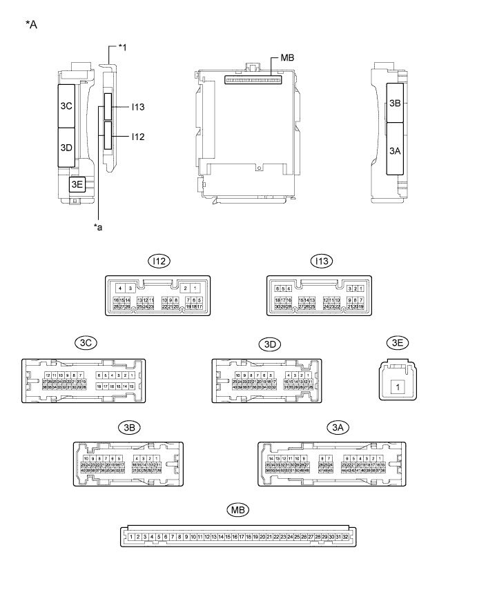
Text in Illustration *A Main Body ECU (Multiplex Network Body ECU) with 2 connectors - - *1 Main Body ECU (Multiplex Network Body ECU) - - *a 2 connectors - - 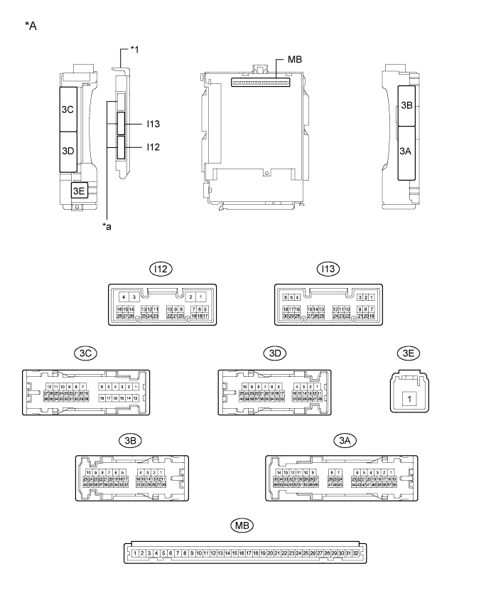
Text in Illustration *A Main Body ECU (Multiplex Network Body ECU) with 3 connectors - - *1 Main Body ECU (Multiplex Network Body ECU) - - *a 3 connectors - -
-
Remove the main body ECU (multiplex network body ECU) from the instrument panel junction block assembly Click here.
-
Reconnect the instrument panel junction block assembly connectors.
-
Measure the voltage and resistance according to the value(s) in the table below.
Tech Tips
Measure the values on the wire harness side with the connectors disconnected.
Terminal No. (Symbol) Wiring Color Terminal Description Condition Specified Condition MB-11 (GND1) - Body ground - Ground Always Below 1 Ω MB-30 (BECU) - Body ground - Auxiliary battery power supply Always 11 to 14 V I12-3 (GND2) - Body ground W-B - Body ground Ground Always Below 1 Ω MB-29 (ACC) - Body ground - ACC power supply Power switch on (ACC) 11 to 14 V MB-29 (ACC) - Body ground - ACC power supply Power switch off Below 1 V MB-31 (ALTB) - Body ground - Auxiliary battery power supply Always 11 to 14 V MB-32 (IG) - Body ground - Power switch power supply Power switch on (IG) 11 to 14 V MB-32 (IG) - Body ground - Power switch power supply Power switch off Below 1 V -
Install the main body ECU (multiplex network body ECU) to the instrument panel junction block assembly Click here.
-
Measure the voltage and check for pulses according to the value(s) in the table below.
Terminal No. (Symbol) Wiring Color Terminal Description Condition Specified Condition 3C-15 (FLCY) - Body ground L - Body ground Front door courtesy switch LH input Front door LH open Below 1 V 3C-15 (FLCY) - Body ground L - Body ground Front door courtesy switch LH input Front door LH closed 11 to 14 V I13-19 (FRCY) - Body ground SB - Body ground Front door courtesy switch RH input Front door RH open Below 1 V I13-19 (FRCY) - Body ground SB - Body ground Front door courtesy switch RH input Front door RH closed 11 to 14 V I13-11 (L2) - Body ground R - Body ground Driver door key-linked lock input Driver door key cylinder turned to lock Below 1 V I13-11 (L2) - Body ground R - Body ground Driver door key-linked lock input Driver door key cylinder off Pulse generation I13-24 (UL3) - Body ground GR - Body ground Driver door key-linked unlock input Driver door key cylinder turned to unlock Below 1 V I13-24 (UL3) - Body ground GR - Body ground Driver door key-linked unlock input Driver door key cylinder off Pulse generation If the result is not as specified, the main body ECU (multiplex network body ECU) or instrument panel junction block assembly may be malfunctioning.
-
-
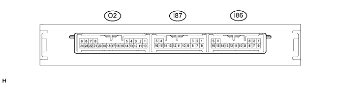
CHECK CERTIFICATION ECU (SMART KEY ECU ASSEMBLY) (w/ Smart Key System)
-
Disconnect the I86 and I87 certification ECU (smart key ECU assembly) connector.
-
Measure the voltage and resistance according to the value(s) in the table below.
Tech Tips
Measure the values on the wire harness side with the connector disconnected.
Terminal No. (Symbol) Wiring Color Terminal Description Condition Specified Condition I87-5 (+B) - Body ground SB - Body ground +B power supply Always 11 to 14 V I86-1 (E) - Body ground W-B - Body ground Ground Always Below 1 Ω -
Reconnect the I86 and I87 certification ECU (smart key ECU assembly) connector.
-
Measure the voltage and check for pulses according to the value(s) in the table below.
Terminal No. (Symbol) Wiring Color Terminal Description Condition Specified Condition I87-16 (IG) - Body ground LG - Body ground IG power supply Power switch off Below 1 V I87-16 (IG) - Body ground LG - Body ground IG power supply Power switch on (IG) 11 to 14 V O2-15 (RCO) - I86-1 (E) G - W-B Door control receiver power source
-
Power switch off
-
Transmitter switch not pressed
Below 1 V O2-15 (RCO) - I86-1 (E) G - W-B Door control receiver power source
-
Power switch off
-
Lock or unlock transmitter switch pressed
4.5 to 5.5 V O2-6 (RDAM) - I86-1 (E) Y - W-B Door control receiver data input signal Power switch off Pulse between 11 to 14 V occurs regularly -
-