AIR CONDITIONING PANEL INSTALLATION

-
INSTALL AIR CONDITIONING CONTROL ASSEMBLY
-
Engage the 2 clips to install the air conditioning control assembly.
-
-
INSTALL NO. 1 RADIO RECEIVER BRACKET
-
w/o Satellite Radio:
-
Install the No. 1 radio receiver bracket with the 5 screws.
-
-
w/ Satellite Radio:
-
Install the No. 1 radio receiver bracket with the 7 screws.
-
-
-
INSTALL NO. 2 RADIO RECEIVER BRACKET
-
w/o Satellite Radio:
-
Install the No. 2 radio receiver bracket with the 5 screws.
-
-
w/ Satellite Radio:
-
Install the No. 2 radio receiver bracket with the 7 screws.
-
-
-
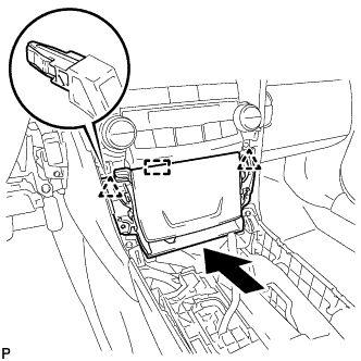
INSTALL RADIO RECEIVER ASSEMBLY WITH AIR CONDITIONING CONTROL ASSEMBLY (w/o Navigation System)
-
Connect each connector.
-
Engage the 4 clips to the vehicle body to temporarily install the radio receiver assembly with air conditioning control assembly.
-
Install the radio receiver assembly with air conditioning control assembly with the 4 bolts and 2 screws.
-
-
INSTALL NAVIGATION RECEIVER ASSEMBLY WITH AIR CONDITIONING CONTROL ASSEMBLY (w/ Navigation System)
-
Connect each connector.
-
Engage the 4 clips to the vehicle body to temporarily install the navigation receiver assembly with air conditioning control assembly.
-
Install the navigation receiver assembly with air conditioning control assembly with the 4 bolts and 2 screws.
-
-
INSTALL UPPER CONSOLE PANEL SUB-ASSEMBLY
-
Connect each connector.
-
Engage the guide and 2 clips as shown in the illustration.
-
Install the upper console panel sub-assembly with the 2 screws <C> or <D>.
-
-
INSTALL NO. 1 SPEAKER OPENING COVER ASSEMBLY
-
Connect the connector.
-
Engage the clamp.
-
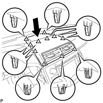
Engage the 11 clips to install the No. 1 speaker opening cover assembly as shown in the illustration.
-
-
INSTALL REAR CONSOLE UPPER PANEL SUB-ASSEMBLY
-
Engage the 6 clips.
-
Install the rear console upper panel sub-assembly with the 2 screws <C> or <D>.
-
Connect the connector.
-
Move the shift lever to P.
-
-
INSTALL SHIFT LEVER KNOB SUB-ASSEMBLY
-
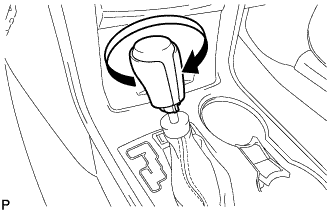
Turn the shift lever knob sub-assembly clockwise to install the shift lever knob sub-assembly.
-
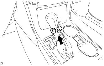
Engage the 2 claws as shown in the illustration.
-
-
INSTALL UPPER CONSOLE BOX SUB-ASSEMBLY
-
Connect each connector.
-
Engage the 4 clips to install the upper console box sub-assembly.
-
-
CONNECT CABLE TO AUXILIARY BATTERY NEGATIVE TERMINAL (w/ Navigation System)
Note
When disconnecting the cable, some systems need to be initialized after the cable is reconnected Click here.
-
INSTALL LUGGAGE TRIM SERVICE HOLE COVER (w/ Navigation System)
-
Engage the claw to connect the luggage trim service hole cover.
-