BLOWER UNIT REASSEMBLY

-
INSTALL BLOWER MOTOR WITH FAN SUB-ASSEMBLY
-
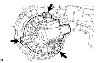
Install the blower motor with fan sub-assembly with the 3 screws.
-
-
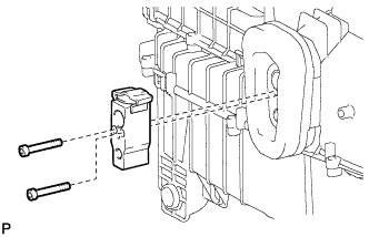
INSTALL NO. 1 BLOWER DAMPER SERVO SUB-ASSEMBLY
-
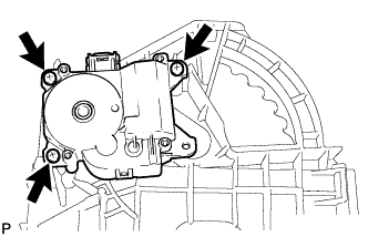
Install the No. 1 blower damper servo sub-assembly with the 3 screws.
-
-
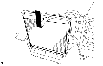
INSTALL CLEAN AIR FILTER
-
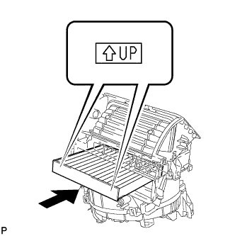
Install the clean air filter as shown in the illustration.
-
-
INSTALL AIR FILTER COVER PLATE
-
Engage the 2 claws to install the air filter cover plate.
-
-
INSTALL AIR DUCT SUB-ASSEMBLY
-
Engage the 4 claws to install the air duct sub-assembly.
-
-
INSTALL DRAIN COOLER HOSE
-
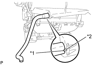
Text in Illustration *1 Hose Notch *2 Blower Case Assembly Rib Install the drain cooler hose to the blower case assembly.
-
-
INSTALL NO. 1 COOLER EVAPORATOR SUB-ASSEMBLY
-
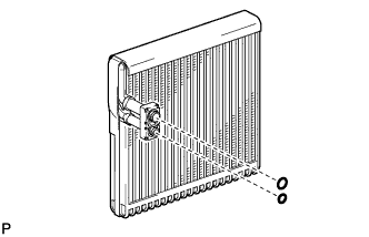
Sufficiently apply compressor oil to 2 new O-rings and the fitting surfaces. Install the 2 O-rings to the No. 1 cooler evaporator sub-assembly.
Compressor oil ND-OIL 11 or equivalent -
Install the No. 1 cooler evaporator sub-assembly to the blower assembly.
-
-
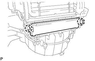
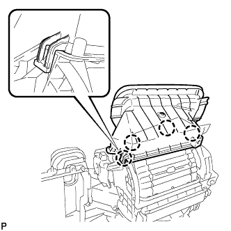
INSTALL NO. 1 COOLER THERMISTOR
-
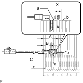
Text in Illustration *a Fixed Part *b Sensor Part Install the No. 1 cooler thermistor as shown in the illustration.
Part Length A 34.3 mm 1.35 in. B 20.9 mm 0.82 in. C 50 mm 1.96 in. Note
-
Be sure to insert the thermistor only once because reinserting it into the same position will not allow it to be firmly secured.
-
When reusing the evaporator, insert the thermistor one row next to the one that has been used previously (X in the illustration).
-
After inserting the thermistor, do not apply excessive force to the wire.
-
Directly insert the thermistor until the edge of plastic case "a" comes into contact with evaporator "b".
-
-
Engage the 2 clamps.
-
-
INSTALL COOLER EXPANSION VALVE
-
Using a 4 mm hexagon wrench, install the cooler expansion valve with the 2 hexagon bolts.
- Torque:
- 3.5 N*m { 36 kgf*cm, 31 in.*lbf }
-