AIR CONDITIONING UNIT REMOVAL

Note
Make sure to select FACE mode before disconnecting the cable from the negative (-) auxiliary battery terminal.
-
RECOVER REFRIGERANT FROM AIR CONDITIONING SYSTEM
-
Turn the power switch on (READY).
-
Turn the A/C switch on.
-
Operate the cooler compressor under the conditions shown below:
Item Condition Engine Speed Idling Operating Time 3 minutes or more A/C Switch Status ON Blower Switch Status HI Set Temperature MAX COOL This cause most of the compressor oil from the various components of the A/C system to collect in the A/C compressor.
Tech Tips
It is not necessary to operate the cooler compressor if the A/C does not operate because of compressor lock etc.
-
Turn the power switch off.
-
Recover the refrigerant from the air conditioning system using a refrigerant recovery unit.
Tech Tips
Use the refrigerant recover unit in accordance with the manufacturer's instruction manual.
-
-
REMOVE WINDSHIELD WIPER MOTOR AND LINK ASSEMBLY
-
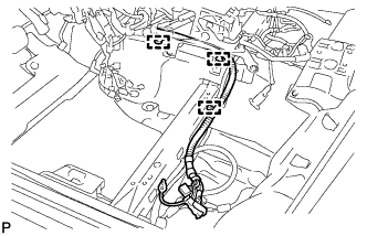
REMOVE FRONT OUTER COWL TOP PANEL SUB-ASSEMBLY
-
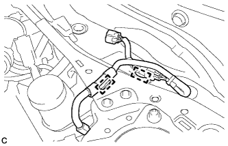
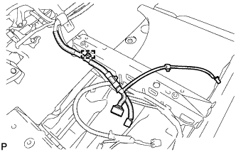
Disengage the 2 clamps and separate the wire harness from the front outer cowl top panel sub-assembly.
-
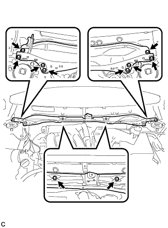
Remove the 10 bolts and front outer cowl top panel sub-assembly.
-
-
DISCONNECT HEATER OUTLET WATER HOSE
-
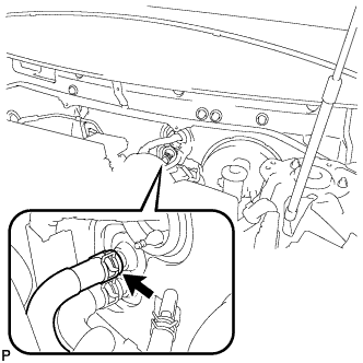
Using pliers, grip the claws of the clip and slide the clip to disconnect the heater outlet water hose.
Note
-
Do not apply excessive force to the heater outlet water hose.
-
Prepare a drain pan or cloth in case the coolant leaks.
-
-
-
DISCONNECT HEATER INLET WATER HOSE
-
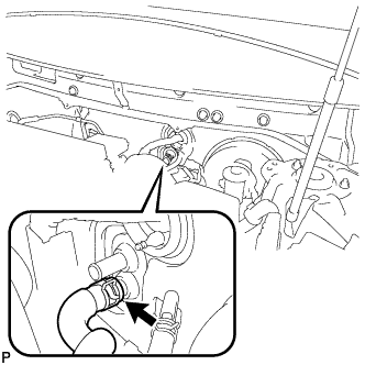
Using pliers, grip the claws of the clip and slide the clip to disconnect the heater inlet water hose.
Note
-
Do not apply excessive force to the heater inlet water hose.
-
Prepare a drain pan or cloth in case the coolant leaks.
-
-
-
DISCONNECT SUCTION HOSE SUB-ASSEMBLY
-
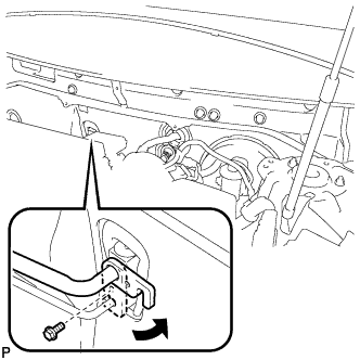
Remove the bolt and rotate the hook connector.
-
Disconnect the suction hose sub-assembly.
-
Remove the O-ring from the suction hose sub-assembly.
Note
Seal the openings of the disconnected parts using vinyl tape to prevent the entry of moisture and foreign matter.
-
-
DISCONNECT AIR CONDITIONER TUBE AND ACCESSORY ASSEMBLY
-
Disconnect the air conditioner tube and accessory assembly.
-
Remove the O-ring from the air conditioner tube and accessory assembly.
Note
Seal the openings of the disconnected parts using vinyl tape to prevent the entry of moisture and foreign matter.
-
-
REMOVE FRONT SEAT ASSEMBLY LH (for Manual Seat)
-
REMOVE FRONT SEAT ASSEMBLY LH (for Power Seat)
-
REMOVE AUDIO AMPLIFIER COVER (for 10 Speakers)
-
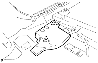
Using a clip remover, remove the 2 clips and audio amplifier cover.
-
-
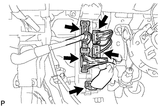
REMOVE STEREO COMPONENT AMPLIFIER ASSEMBLY WITH BRACKET (for 10 Speakers)
-
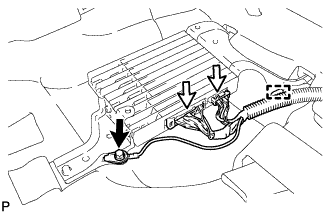
Remove the bolt and disconnect the ground wire.
-
Disconnect each connector and disengage the clamp.
-
Remove the bolt.
-
Disengage the 2 guides and remove the stereo component amplifier assembly with bracket.
-
-
REMOVE FRONT SEAT ASSEMBLY RH (for Manual Seat)
Tech Tips
Use the same procedure for the RH side and LH side.
-
REMOVE FRONT SEAT ASSEMBLY RH (for Power Seat)
Tech Tips
Use the same procedure for the RH side and LH side.
-
REMOVE AUDIO AMPLIFIER COVER (w/ Manual (SOS) Switch)
-
Using a clip remover, remove the 2 clips and audio amplifier cover.
-
-
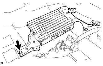
REMOVE DCM (TELEMATICS TRANSCEIVER) WITH BACK-UP BATTERY (w/ Manual (SOS) Switch)
-
Disconnect each connector.
-
Disengage the 3 clamps.
-
Remove the bolt.
-
Disengage the 2 guides and remove the DCM (telematics transceiver) with back-up battery.
-
-
REMOVE INSTRUMENT PANEL SAFETY PAD ASSEMBLY
-
REMOVE STEERING POST ASSEMBLY
-
REMOVE POWER MANAGEMENT CONTROL ECU
-
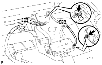
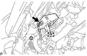
REMOVE INSTRUMENT PANEL JUNCTION BLOCK ASSEMBLY
-
Disconnect the 5 connectors.
-
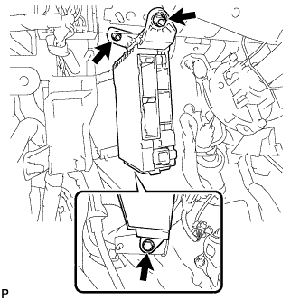
Remove the bolt and 2 nuts, and disconnect the instrument panel junction block assembly.
-
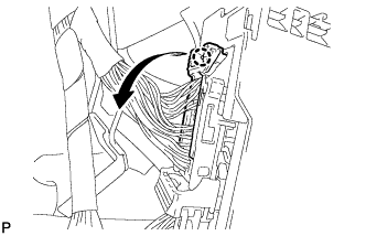
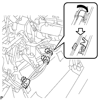
Disengage the claw and disconnect the connector as shown in the illustration.
-
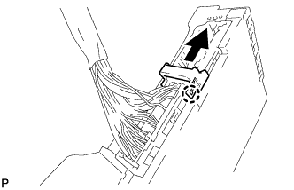
Disengage the claw and release the connector lock as shown in the illustration.
-
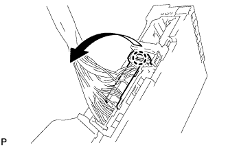
Disengage the claw and disconnect the connector as shown in the illustration to remove the instrument panel junction block assembly.
-
-
REMOVE VEHICLE APPROACHING SPEAKER CONTROLLER
-
Disconnect the connector.
-
Remove the nut.
-
Disengage the guide to remove the vehicle approaching speaker controller.
-
-
REMOVE CERTIFICATION ECU (SMART KEY ECU ASSEMBLY) (w/o ECU Integration Box RH)
-
w/ ECU Integration Box RH:
-
Disengage the 2 claws and remove the certification ECU (smart key ECU assembly).
-
-
w/o ECU Integration Box RH:
-
Disconnect each connector.
-
Remove the bolt, nut and certification ECU (smart key ECU assembly).
-
-
-
REMOVE ECU INTEGRATION BOX RH (w/ ECU Integration Box RH)
-
Disconnect each connector and disengage the clamp.
-
Remove the bolt, 2 nuts and the ECU integration box RH.
-
-
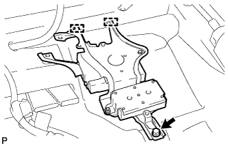
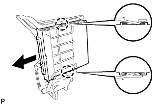
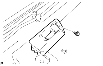
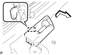
REMOVE AIR CONDITIONING AMPLIFIER ASSEMBLY
-
Disconnect each connector.
-
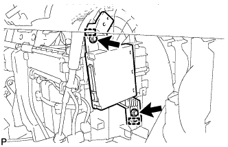
Remove the 2 screws.
-
Disengage the 2 guides and remove the air conditioning amplifier assembly.
-
-
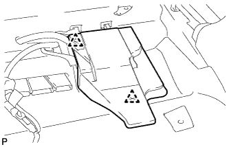
REMOVE GLASS BREAKAGE SENSOR ECU (w/ Glass Breakage Sensor)
-
Disconnect the connector.
-
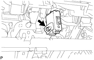
Remove the nut and glass breakage sensor ECU.
-
-
REMOVE FLOOR CARPET HOOK
-
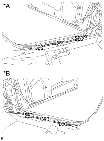
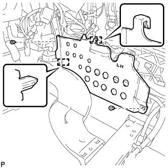
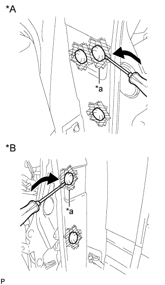
Text in Illustration *A for LH Side *B for RH Side Disengage the 6 guides.
-
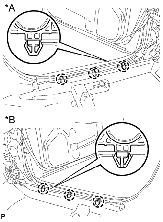
Text in Illustration *A for LH Side *B for RH Side Disengage the 6 claws and remove the 6 floor carpet hooks.
-
-
DISCONNECT FUEL LID LOCK OPEN LEVER SUB-ASSEMBLY
-
Remove the screw.
-
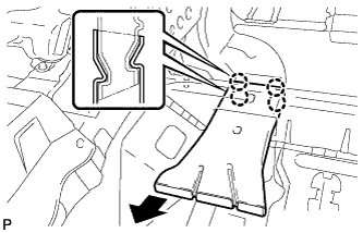
Disengage the guide to disconnect the fuel lid lock open lever sub-assembly as shown in the illustration.
-
-
REMOVE FRONT FLOOR CARPET LH
-
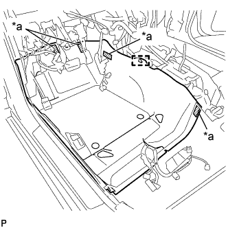
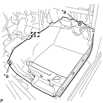
Text in Illustration *a Fastener Disengage the guide and each fastener, and remove the front floor carpet LH.
-
-
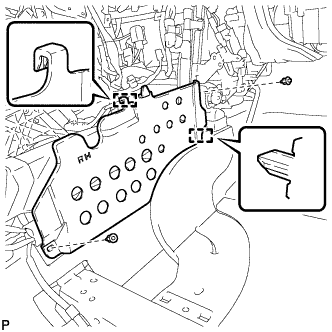
REMOVE REAR NO. 4 AIR DUCT
-
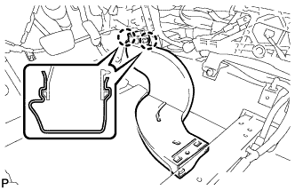
Disengage the 4 claws to remove the rear No. 4 air duct as shown in the illustration.
-
-
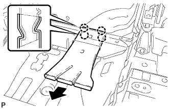
REMOVE FLOOR CARPET BRACKET LH
-
Remove the 2 clips.
-
Disengage the 2 guides to remove the floor carpet bracket LH.
-
-
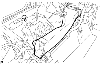
REMOVE REAR NO. 3 AIR DUCT
-
Disengage the 2 claws to remove the rear No. 3 air duct.
-
-
REMOVE FRONT FLOOR CARPET RH
-
Text in Illustration *a Fastener Disengage the guide and each fastener, and remove the front floor carpet RH.
-
-
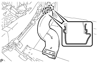
REMOVE REAR NO. 2 AIR DUCT
-
Disengage the 4 claws to remove the rear No. 2 air duct as shown in the illustration.
-
-
REMOVE FLOOR CARPET BRACKET RH
-
Remove the 2 clips.
-
Disengage the 2 guides to remove the floor carpet bracket RH.
-
-
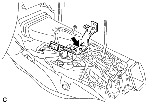
REMOVE REAR NO. 1 AIR DUCT
-
Disengage the 2 claws to remove the rear No. 1 air duct.
-
-
REMOVE NO. 1 CONSOLE BOX MOUNTING BRACKET
-
Remove the screw and No. 1 console box mounting bracket from the lower shift lever assembly.
-
-
REMOVE NO. 1 CONSOLE BOX DUCT (w/ Rear Register Duct)
-
Remove the clip and No. 1 console box duct.
-
-
REMOVE ROOM TEMPERATURE SENSOR (COOLER THERMISTOR)
-
Disconnect the cooler thermistor hose and connector, and remove the room temperature sensor (cooler thermistor).
-
-
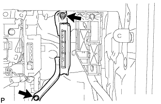
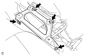
REMOVE INSTRUMENT PANEL TO COWL BRACE SUB-ASSEMBLY
-
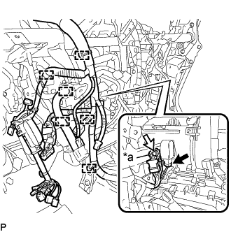
Text in Illustration *a Earth Wire Disconnect the connector.
-
Disengage each clamp.
-
Remove the bolt and disconnect the earth wire.
-
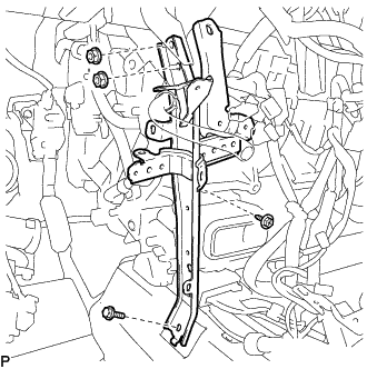
Remove the bolt and 2 nuts.
-
Remove the screw and instrument panel to cowl brace sub-assembly.
-
-
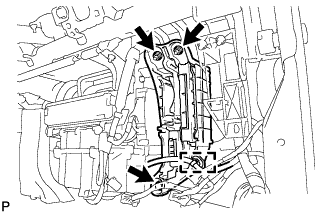
REMOVE NO. 2 INSTRUMENT PANEL BRACE SUB-ASSEMBLY
-
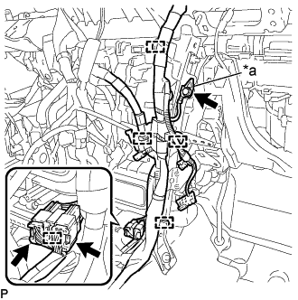
Text in Illustration *a Earth Wire Disconnect each connector.
-
Disengage each clamp.
-
Remove the bolt and disconnect the earth wire.
-
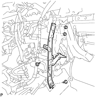
Remove the bolt and 2 nuts.
-
Remove the screw and No. 2 instrument panel brace sub-assembly.
-
-
REMOVE INSTRUMENT PANEL SAFETY PAD CAP
-
Text in Illustration *A for LH Side *B for RH Side *a Protective Tape Put protective tape around the 5 instrument panel safety pad caps.
-
Using a screwdriver, remove the 5 instrument panel safety pad caps as shown in the illustration.
-
-
REMOVE FRONT LOWER PANEL PACKING
-
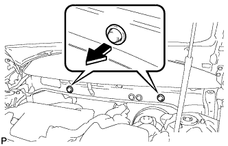
Remove the 2 front lower panel packings as shown in the illustration.
-
-
REMOVE INSTRUMENT PANEL REINFORCEMENT ASSEMBLY WITH AIR CONDITIONING UNIT
Note
-
Be sure to support the air conditioning unit assembly when removing it because failure to do so may cause the bracket of the air conditioning unit assembly to break.
-
When disassembling the air conditioning unit, eliminate static electricity by touching the vehicle body to prevent the components from being damaged.
-
for 10 Speakers:
-
Disengage the 3 clamps.
-
-
w/ Manual (SOS) Switch:
-
Disengage the clamp.
-
-
Disengage the 3 claws to open the 3 clamps.
-
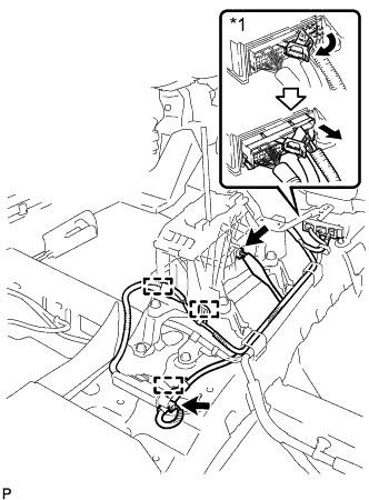
Text in Illustration *1 Center Airbag Sensor Connector Disconnect the center airbag sensor connectors from the center airbag sensor assembly as shown in the illustration.
Note
When disconnecting any airbag connector, take care not to damage the airbag wire harness.
-
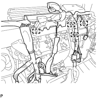
Disconnect each connector.
-
Disengage each clamp.
-
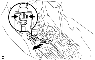
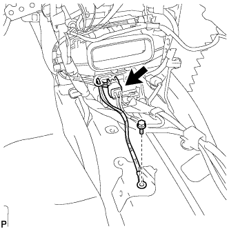
Disconnect the end of the transmission control cable assembly from the lower shift lever assembly.
-
Disengage the 2 claws to disconnect the transmission control cable assembly from the lower shift lever assembly.
-
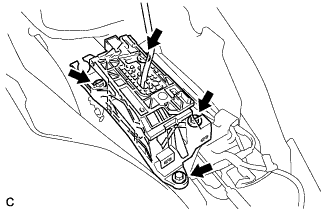
Remove the 4 bolts and lower shift lever assembly from the shift lever support.
-
Remove the 4 bolts and shift lever support from the vehicle body.
-
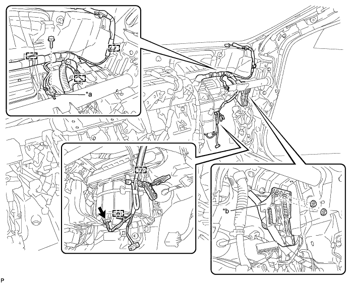
Remove the bolt.
-
Disconnect the connector.
-
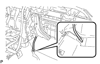
Using a screwdriver, disengage the 2 claws to unlock the retainer as shown in the illustration.
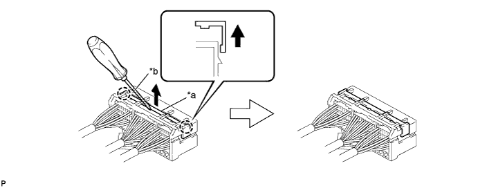
Text in Illustration *a Retainer *b Protective Tape -
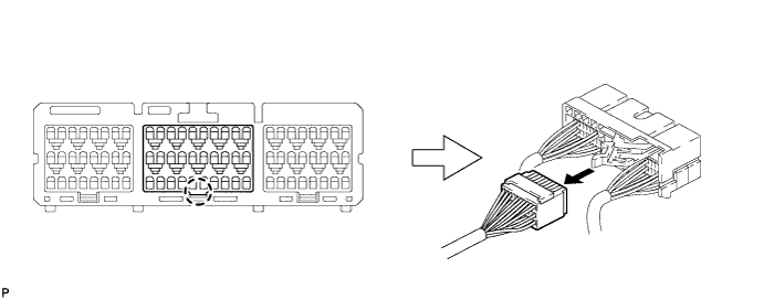
Disengage the claw and disconnect the airbag connector as shown in the illustration.
-
Disengage each clamp.
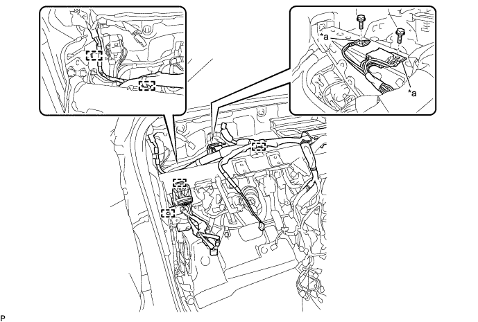
Text in Illustration *a Earth Wire - - -
Remove the 2 bolts and disconnect the 2 earth wires.
-
Disengage each clamp.
-
Remove the bolt and disconnect the earth wire.
Text in Illustration *a Earth Wire *b Connector Holder -
Remove the 2 nuts and disconnect the connector holder.
-
Disconnect the connector.
-
Disengage each clamp.
-
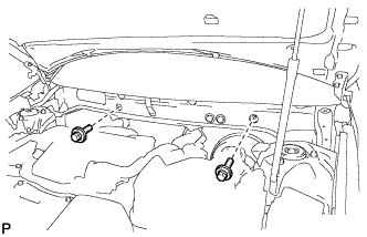
Remove the 2 bolts.
-
Disconnect the drain cooler hose.
-
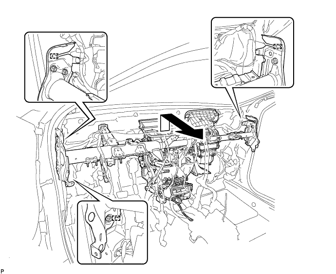
Remove the 6 bolts and nut as shown in the illustration.
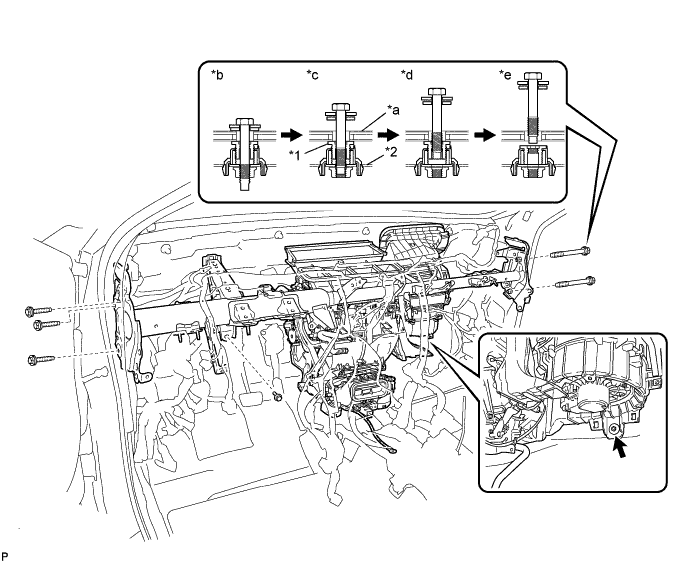
Text in Illustration *1 Movable Collar *2 Instrument Panel Reinforcement Assembly *a Vehicle Body *b Step 1 *c Step 2 *d Step 3 *e Step 4 - - -
Disengage the 3 guides and remove the instrument panel reinforcement assembly with air conditioning unit as shown in the illustration.
-
-
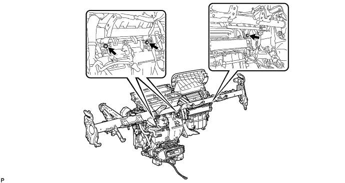
REMOVE AIR CONDITIONING UNIT ASSEMBLY
-
Remove the 3 bolts and air conditioning unit assembly from the instrument panel reinforcement assembly.
-