CONDENSER REMOVAL

-
PRECAUTION
Note
After turning the power switch off, waiting time may be required before disconnecting the cable from the negative (-) auxiliary battery terminal. Therefore, make sure to read the disconnecting the cable from the negative (-) auxiliary battery terminal notices before proceeding with work Click here.
-
RECOVER REFRIGERANT FROM AIR CONDITIONING SYSTEM
-
Turn the power switch on (READY).
-
Turn the A/C switch on.
-
Operate the cooler compressor under the conditions shown below:
Item Condition Engine Speed Idling Operating Time 3 minutes or more A/C Switch Status ON Blower Switch Status HI Set Temperature MAX COOL This cause most of the compressor oil from the various components of the A/C system to collect in the A/C compressor.
Tech Tips
It is not necessary to operate the cooler compressor if the A/C does not operate because of compressor lock etc.
-
Turn the power switch off.
-
Recover the refrigerant from the air conditioning system using a refrigerant recovery unit.
Tech Tips
Use the refrigerant recover unit in accordance with the manufacturer's instruction manual.
-
-
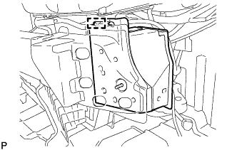
REMOVE LUGGAGE TRIM SERVICE HOLE COVER
-
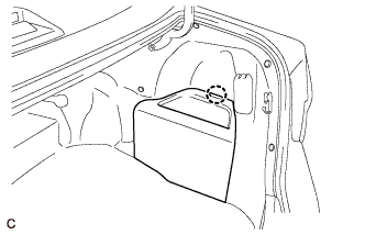
Disengage the claw to remove the luggage trim service hole cover.
-
-
DISCONNECT CABLE FROM AUXILIARY BATTERY NEGATIVE TERMINAL
Note
When disconnecting the cable, some systems need to be initialized after the cable is reconnected Click here.
-
REMOVE FRONT BUMPER ASSEMBLY
-
REMOVE FRONT BUMPER ENERGY ABSORBER
-
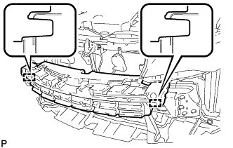
Disengage the 2 guides and remove the front bumper energy absorber.
-
-
REMOVE NO. 2 FRONT BUMPER SUPPORT SPACER SUB-ASSEMBLY
-
Disengage the clamp.
-
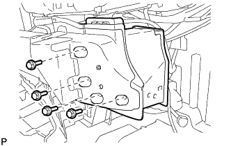
Remove the 4 bolts.
-
Disengage the guide and remove the No. 2 front bumper support spacer sub-assembly.
-
-
REMOVE FRONT BUMPER REINFORCEMENT SUB-ASSEMBLY
-
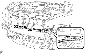
Disengage each clamp.
-
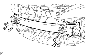
Remove the 6 bolts and front bumper reinforcement sub-assembly.
-
-
REMOVE MILLIMETER WAVE RADAR SENSOR ASSEMBLY (w/ Dynamic Radar Cruise Control System)
-
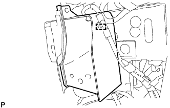
REMOVE INLET AIR CLEANER ASSEMBLY
-
Remove the 2 bolts and inlet air cleaner assembly.
-
-
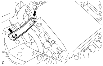
REMOVE HOOD LOCK ASSEMBLY
-
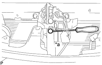
Text in Illustration *a Protective Tape Using a screwdriver, remove the hood lock nut cap.
Tech Tips
Tape the screwdriver tip before use.
-
w/ Engine Hood Courtesy Switch:
-
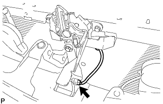
Disconnect the connector.
-
-
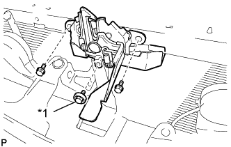
Text in Illustration *1 Hood Lock Bolt Remove the 2 bolts and hood lock bolt.
-
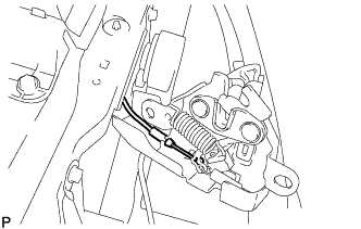
Disconnect the hood lock control cable assembly and remove the hood lock assembly.
-
-
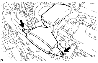
REMOVE NO. 5 INVERTER BRACKET
-
Remove the 2 bolts and No. 5 inverter bracket.
-
-
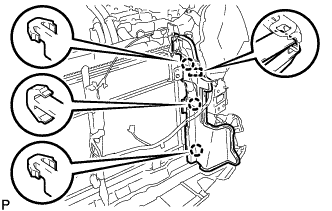
REMOVE UPPER RADIATOR SUPPORT
-
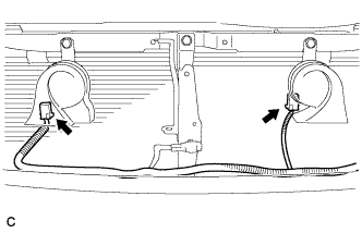
Disconnect the 2 connectors.
-
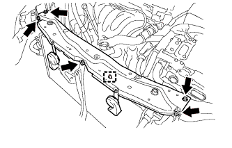
Disconnect the hood lock control cable clamp and remove the 5 bolts and upper radiator support.
-
Remove the 2 radiator support cushions.
-
-
REMOVE RADIATOR SIDE DEFLECTOR RH
-
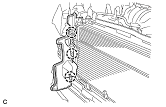
Disengage the 3 claws and remove the radiator side deflector RH.
-
-
REMOVE RADIATOR SIDE DEFLECTOR LH
-
Disengage the 3 claws and guide, and remove the radiator side deflector LH.
-
-
DISCONNECT NO. 1 COOLER REFRIGERANT DISCHARGE HOSE
-
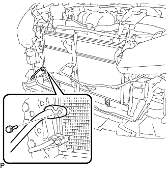
Remove the bolt and disconnect the No. 1 cooler refrigerant discharge hose from the cooler condenser assembly.
-
Remove the O-ring from the No. 1 cooler refrigerant discharge hose.
Note
Seal the openings of the disconnected parts using vinyl tape to prevent entry of moisture and foreign matter.
-
-
DISCONNECT AIR CONDITIONER TUBE AND ACCESSORY ASSEMBLY
-
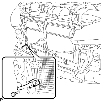
Remove the bolt and disconnect the air conditioner tube and accessory assembly from the cooler condenser assembly.
-
Remove the O-ring from the air conditioner tube and accessory assembly.
Note
Seal the openings of the disconnected parts using vinyl tape to prevent entry of moisture and foreign matter.
-
-
REMOVE COOLER CONDENSER ASSEMBLY
-
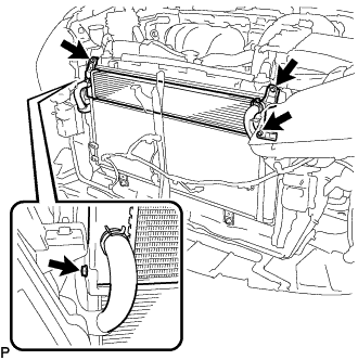
Remove the 4 bolts.
-
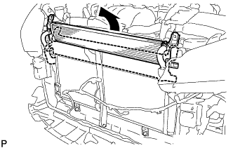
Pull the radiator assembly in the direction indicated by the arrow.
-
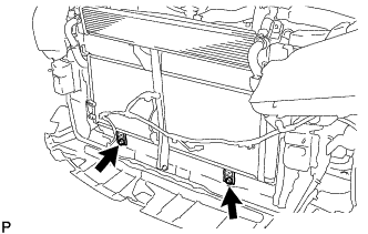
Remove the 2 bolts.
-
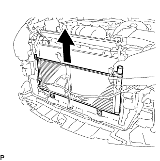
Remove the cooler condenser assembly as shown in the illustration.
-