PRE-COLLISION SYSTEM Pre-collision System Cancel Switch Circuit
DESCRIPTION
Each time the pre-collision system cancel switch assembly is pressed, the pre-collision system sensitivity indicator on the multi-information display changes and the sensitivity of the pre-collision system is changed in 3 levels. Pressing and holding the pre-collision system cancel switch assembly cancels the pre-collision system.
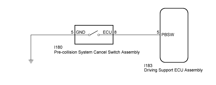
WIRING DIAGRAM
INSPECTION PROCEDURE
Note
When replacing the driving support ECU assembly, always replace it with a new one. If a driving support ECU assembly which was installed to another vehicle is used, the information stored in the driving support ECU assembly will not match the information from the vehicle. As a result, a DTC may be stored.
PROCEDURE
-
READ VALUE USING TECHSTREAM (PCS OFF SWITCH)
-
Connect the Techstream to the DLC3.
-
Turn the power switch on (IG).
-
Turn the Techstream on.
-
Enter the following menus: Body Electrical / Pre-Collision 2 / Data List.
-
Read the Data List according to the display on the Techstream.
Pre-Collision 2 Tester Display Measurement Item/Range Normal Condition Diagnostic Note PCS OFF Switch Pre-collision system cancel switch assembly status/ON or OFF ON: Pre-collision system cancel switch assembly on
OFF: Pre-collision system cancel switch assembly off
- OK When the pre-collision system cancel switch assembly is operated, the display changes as shown above.
NG 
INSPECT PRE-COLLISION SYSTEM CANCEL SWITCH ASSEMBLY Click here
OK 
PROCEED TO NEXT SUSPECTED AREA SHOWN IN PROBLEM SYMPTOMS TABLE Click here
-
-
INSPECT PRE-COLLISION SYSTEM CANCEL SWITCH ASSEMBLY
-
Remove the pre-collision system cancel switch assembly Click here.
-
Inspect the pre-collision system cancel switch assembly Click here.
NG 
REPLACE PRE-COLLISION SYSTEM CANCEL SWITCH ASSEMBLY Click here
OK 
-
-
CHECK HARNESS AND CONNECTOR (DRIVING SUPPORT ECU ASSEMBLY - PRE-COLLISION SYSTEM CANCEL SWITCH ASSEMBLY)
-
Disconnect the I183 driving support ECU assembly connector.
-
Disconnect the I180 pre-collision system cancel switch assembly connector.
-
Measure the resistance according to the value(s) in the table below.
Standard Resistance Tester Connection Condition Specified Condition I183-5 (PBSW) - I180-8 Always Below 1 Ω I183-5 (PBSW) or I180-8 - Body ground Always 10 kΩ or higher -
Reconnect the I180 pre-collision system cancel switch assembly connector.
-
Reconnect the I183 driving support ECU assembly connector.
NG
REPAIR OR REPLACE HARNESS OR CONNECTOR
OK
-
-
CHECK HARNESS AND CONNECTOR (PRE-COLLISION SYSTEM CANCEL SWITCH ASSEMBLY - BODY GROUND)
-
Disconnect the I180 pre-collision system cancel switch assembly connector.
-
Measure the resistance according to the value(s) in the table below.
Standard Resistance Tester Connection Condition Specified Condition I180-5 - Body ground Always Below 1 Ω -
Reconnect the I180 pre-collision system cancel switch assembly connector.
NG
REPAIR OR REPLACE HARNESS OR CONNECTOR
OK
REPLACE DRIVING SUPPORT ECU ASSEMBLY Click here
-