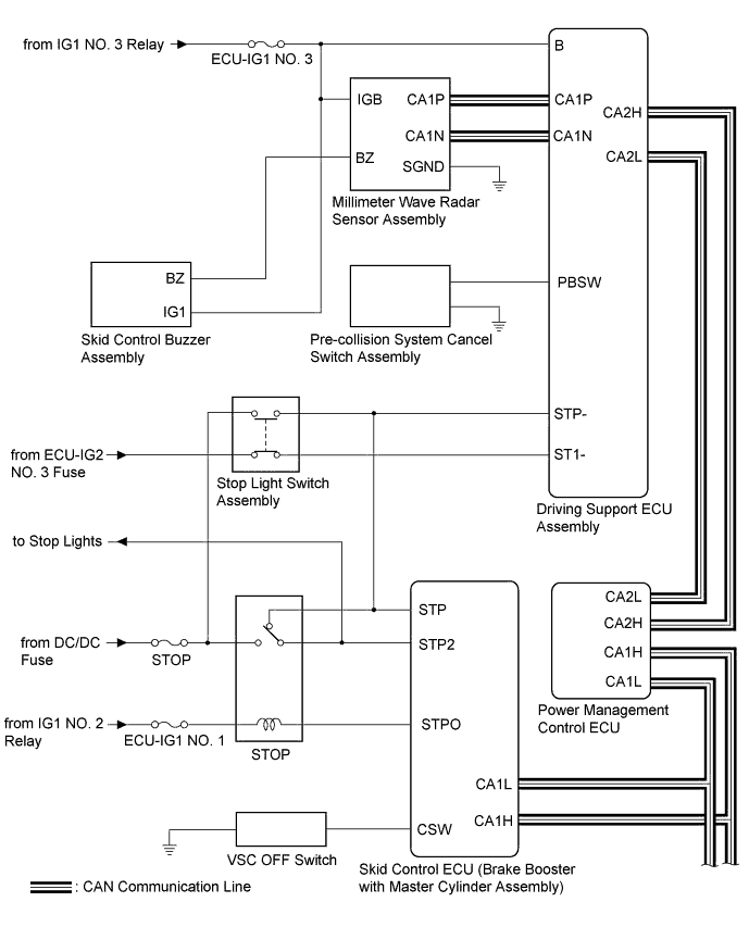
| Driving Support ECU Assembly |
Skid Control ECU (Brake Booster with Master Cylinder Assembly) |
|
CAN |
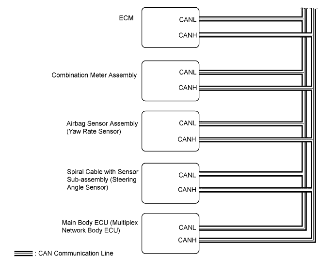
| Combination Meter Assembly |
-
Pre-collision system malfunction signal
-
Warning signal
-
Pre-collision system off signal
-
Sensitivity display signal
|
CAN |
| Millimeter Wave Radar Sensor Assembly |
|
CAN |
| Skid Control ECU (Brake Booster with Master Cylinder Assembly) |
Driving Support ECU Assembly |
Vehicle speed signal |
CAN |
| Airbag Sensor Assembly (Yaw Rate Sensor) |
Driving Support ECU Assembly |
Vehicle yaw rate sensor signal |
CAN |
| Main Body ECU (Multiplex Network Body ECU) |
Driving Support ECU Assembly |
Vehicle specification information (destination, steering wheel position) signal |
CAN |
| Spiral Cable with Sensor Sub-assembly (Steering Angle Sensor) |
Driving Support ECU Assembly |
Steering angle sensor signal |
CAN |
| Power Management Control ECU |
Driving Support ECU Assembly |
|
CAN |
| Millimeter Wave Radar Sensor Assembly |
Driving Support ECU Assembly |
|
CAN |