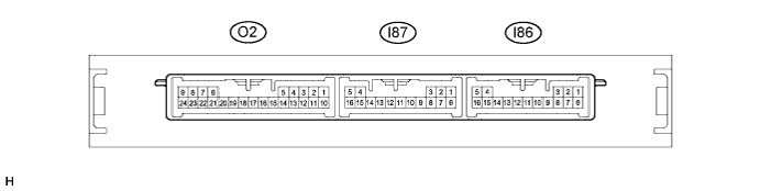
SMART KEY SYSTEM (for Entry Function) TERMINALS OF ECU

-
CHECK CERTIFICATION ECU (SMART KEY ECU ASSEMBLY)
-
Disconnect the O2 and I86 certification ECU (smart key ECU assembly) connector.
-
Measure the voltage and resistance according to the value(s) in the table below.
Tech Tips
Measure the values on the wire harness side with the connector disconnected.
Tester Connection Input/Output Wiring Color Terminal Description Condition Specified Condition Related Data List Item I86-1 (E) - Body ground - W-B - Body ground Ground Always Below 1 Ω - I87-5 (+B) - I86-1 (E) Input SB - W-B +B power supply Power switch off 11 to 14 V - I87-4 (CUTB) - I86-1 (E) Input W -W-B Dark current cut pin* Power switch off 11 to 14 V -
-
*: In order to prevent the vehicle auxiliary battery from being depleted when the vehicle is shipped long distances, a fuse that cuts unnecessary electrical load while the vehicle is being shipped is set in the circuit. If the fuse is removed, the circuit becomes open. If the fuse that is between the vehicle auxiliary battery and terminal CUTB is removed and the circuit is open, the certification ECU (smart key ECU assembly) changes to a certain control mode (example: the transmission of electric waves every 0.25 seconds. that form the detection area stops).
If the result is not as specified, there may be a malfunction on the wire harness side or the fuse is removed.
-
-
Reconnect the O2 and I86 certification ECU (smart key ECU assembly) connector.
-
Measure the voltage according to the value(s) in the table below.
Tester Connection Input/Output Wiring Color Terminal Description Condition Specified Condition Related Data List Item I87-16 (IG) - I86-1 (E) Input LG - W-B IG power supply Power switch off → on (IG) Below 1 V → 11 to 14 V Engine Switch I86-5 (CLG1) - I86-1 (E) Output Y - W-B Output to driver door electrical key antenna
(request signal (challenge) is sent to door electrical key antenna from certification ECU (smart key ECU assembly) to form detection area)
Procedure:
-
Power switch off
-
Electrical key transmitter sub-assembly brought outside vehicle
-
All doors closed
-
Electrical key transmitter sub-assembly not inside vehicle
-
Electrical key transmitter sub-assembly brought inside detection area*1
-
All doors locked through wireless operation
Pulse generation (See waveform 1) Over Head + Driver Side (key diagnostic mode) Procedure:
-
Power switch off
-
Electrical key transmitter sub-assembly brought outside vehicle
-
All doors closed
-
Electrical key transmitter sub-assembly not inside vehicle
-
Electrical key transmitter sub-assembly brought outside detection area*2
-
All doors locked through wireless operation
Pulse generation (See waveform 2) Over Head + Driver Side (key diagnostic mode) I86-4 (CG1B) - I86-1 (E) Output LG - W-B Output to driver door electrical key antenna (terminal on opposite side of component from CLG1 output terminal) Procedure:
-
Power switch off
-
Electrical key transmitter sub-assembly brought outside vehicle
-
All doors closed
-
Electrical key transmitter sub-assembly not inside vehicle
-
All doors locked through wireless operation
Pulse generation (See waveform 2) Over Head + Driver Side (key diagnostic mode) I86-13 (CLG2) - I86-1 (E) Output Y - W-B Output to front passenger door electrical key antenna
(request signal (challenge) is sent to door electrical key antenna from certification ECU (smart key ECU assembly) to form detection area)
Procedure:
-
Power switch off
-
Electrical key transmitter sub-assembly brought outside vehicle
-
All doors closed
-
Electrical key transmitter sub-assembly not inside vehicle
-
Electrical key transmitter sub-assembly brought inside detection area*1
-
All doors locked through wireless operation
Pulse generation (See waveform 1) Over Head + Passenger Side (key diagnostic mode) Procedure:
-
Power switch off
-
Electrical key transmitter sub-assembly brought outside vehicle
-
All doors closed
-
Electrical key transmitter sub-assembly not inside vehicle
-
Electrical key transmitter sub-assembly brought outside detection area*2
-
All doors locked through wireless operation
Pulse generation (See waveform 2) Over Head + Passenger Side (key diagnostic mode) I86-12 (CG2B) - I86-1 (E) Output L - W-B Output to front passenger door electrical key antenna (terminal on opposite side of component from CLG2 output terminal) Procedure:
-
Power switch off
-
Electrical key transmitter sub-assembly brought outside vehicle
-
All doors closed
-
Electrical key transmitter sub-assembly not inside vehicle
-
All doors locked through wireless operation
Pulse generation (See waveform 2) Over Head + Passenger Side (key diagnostic mode) I86-11 (CLG5) - I86-1 (E) Output R - W-B Output to No. 1 indoor electrical key antenna assembly (front floor) Procedure:
-
Power switch off
-
Electrical key transmitter sub-assembly not inside vehicle
-
Door is open
-
Door is closed
-
Within 30 seconds
Pulse generation (See waveform 3) Over Head + Front Room (key diagnostic mode) I86-10 (CG5B) - I86-1 (E) Output W - W-B Output to No. 1 indoor electrical key antenna assembly (front floor) (terminal on opposite side of component from CLG5 output terminal) Procedure:
-
Power switch off
-
Electrical key transmitter sub-assembly not inside vehicle
-
Door is open
-
Door is closed
-
Within 30 seconds
Pulse generation (See waveform 3) Over Head + Front Room (key diagnostic mode) I87-7 (TSW1) - I86-1 (E) Input R - W-B Driver door lock sensor signal input
(Sends signal from door lock sensor on front door outside handle assembly to certification ECU (smart key ECU assembly). Certification ECU (smart key ECU assembly) send 12 V pulse waveform every 40 ms. from terminal TSW. When door lock sensor is touched, the pulse is grounded.
Procedure:
-
Power switch off
-
Electrical key transmitter sub-assembly brought outside vehicle
-
All doors closed
-
Driver door lock sensor not touched → touched
Pulse generation (See waveform 6) D-Door Trigger Switch I87-8 (TSW2) - I86-1 (E) Input V - W-B Front passenger door lock sensor signal input
(Sends signal from door lock sensor on front door outside handle assembly to certification ECU (smart key ECU assembly). Certification ECU (smart key ECU assembly) sends 12 V pulse waveform every 40 ms. from terminal TSW. When door lock sensor is touched, the pulse is grounded.
Procedure:
-
Power switch off
-
Electrical key transmitter sub-assembly brought outside vehicle
-
All doors closed
-
Front passenger door lock sensor not touched → touched
Pulse generation (See waveform 6) P-Door Trigger Switch I86-3 (SEN1) - I86-1 (E) Input LG - W-B Driver door unlock sensor signal input
(when system is in unlock standby mode and touch sensor is touched, door electrical key antenna sends touch sensor input signal (sensing) to certification ECU (smart key ECU assembly))
Procedure:
-
Power switch off
-
Electrical key transmitter sub-assembly brought outside vehicle
-
All doors locked
-
Electrical key transmitter sub-assembly not sufficiently close to vehicle
-
Driver door unlock sensor not touched → touched
Pulse generation (See waveform 6) D-Door Touch Sensor I86-2 (SEN2) - I86-1 (E) Input GR - W-B Front passenger door unlock sensor signal input
(when system is in unlock standby mode and touch sensor is touched, door electrical key antenna sends touch sensor input signal (sensing) to certification ECU (smart key ECU assembly))
Procedure:
-
Power switch off
-
Electrical key transmitter sub-assembly brought outside vehicle
-
All doors locked
-
Electrical key transmitter sub-assembly not sufficiently close to vehicle
-
Front passenger door unlock sensor not touched → touched
Pulse generation (See waveform 6) P-Door Touch Sensor O2-22 (TSW5) - I86-1 (E) Input G - W-B Luggage door opening switch assembly signal input Luggage door opening switch assembly off → on Pulse generation (See waveform 6) Tr/B-Door Unlock SW O2-14 (CLG6) - I86-1 (E) Output W - W-B Output to No. 2 indoor electrical key antenna assembly (rear floor) Procedure:
-
Power switch off
-
Electrical key transmitter sub-assembly not inside vehicle
-
Door is open
-
Door is closed
-
Within 30 seconds
Pulse generation (See waveform 3) Over Head + Rear Room (key diagnostic mode) O2-5 (CG6B) - I86-1 (E) Output B - W-B Output to No. 2 indoor electrical key antenna assembly (rear floor) (terminal on opposite side of component from CLG6 output terminal) Proceed:
-
Power switch off
-
Electrical key transmitter sub-assembly not inside vehicle
-
Door is open
-
Door is closed
-
Within 30 seconds
Pulse generation (See waveform 3) Over Head + Rear Room (key diagnostic mode) O2-4 (CLG7) - I86-1 (E) Output R - W-B Output to No. 3 indoor electrical key antenna assembly (inside luggage compartment) Proceed:
-
Power switch off
-
Electrical key transmitter sub-assembly not inside vehicle
-
All doors closed
-
Driver door lock sensor not touched → touched
Pulse generation (See waveform 4) Over Head + Luggage (inside) (key diagnostic mode) O2-3 (CG7B) - I86-1 (E) Output W - W-B Output to No. 3 indoor electrical key antenna assembly (inside luggage compartment) (terminal on opposite side of component from CLG7 output terminal) Proceed:
-
Power switch off
-
Electrical key transmitter sub-assembly not inside vehicle
-
All doors closed
-
Driver door lock sensor not touched → touched
Pulse generation (See waveform 4) Over Head + Luggage (inside) (key diagnostic mode) I86-15 (POS1) - I86-1 (E) Output P - W-B Driver door unlock sensor power source (12 V (drops when power switch turned on (IG))) Power switch off → on (IG) 9 to 14 V → Below 2 V - I86-16 (POS2) - I86-1 (E) Output B - W-B Front passenger door unlock sensor power source (12 V (drops when power switch turned on (IG))) Power switch off → on (IG) 9 to 14 V → Below 2 V - O2-15 (RCO) - I86-1 (E) Output G - W-B Output to door control receiver
(Power supply for door control receiver. Certification ECU (smart key ECU assembly) outputs 5 V when receiver starts operating.)
Procedure:
-
Power switch off
-
Electrical key transmitter sub-assembly brought outside vehicle
-
Electrical key transmitter sub-assembly brought outside detection area*2 but kept inside wireless function operational area*3
-
Lock or unlock button of electrical key transmitter sub-assembly not pressed → pressed
Pulse generation (See waveform 7) - O2-16 (ASEL) - I86-1 (E) Output L - W-B Wireless charging system stop signal output Proceed:
-
Power switch off
-
Electrical key transmitter sub-assembly inside vehicle
-
Turn the power switch on (ACC)
Below 1 V → 4.5 to 6 V
(within 1 second of power switch turned on (ACC))
- O2-6 (RDAM) - I86-1 (E) Input Y - W-B Door control receiver verifies data received from electrical key transmitter sub-assembly. Door control receiver sends data to ECU and intermittently grounds 12 V signal from certification ECU (smart key ECU assembly). Proceed:
-
Power switch off
-
All doors locked
-
Electrical key transmitter sub-assembly brought outside detection area*2 but kept inside wireless function operational area*3
-
Lock or unlock button of electrical key transmitter sub-assembly not pressed → pressed
Pulse generation (See waveform 8) - O2-7 (CSEL) - I86-1 (E) Output LG - W-B Communication channel switching circuit. Procedure:
-
Power switch off
-
All doors closed
Below 1 V → 4.5 to 6 V → Below 1 V Key diagnostic mode O2-2 (CLG8) - I86-1 (E) Output V - W-B Output to electrical key antenna (outside luggage) Procedure:
-
Power switch off
-
Electrical key transmitter sub-assembly brought outside vehicle
-
All doors closed
-
Luggage door opening switch assembly off → on
Pulse generation (See waveform 5) Over Head + Luggage
or
Luggage + Luggage (key diagnostic mode)
O2-1 (CG8B) - I86-1 (E) Output P - W-B Output to electrical key antenna (outside luggage) (terminal on opposite side of component from CLG8 output terminal) Procedure:
-
Power switch off
-
Electrical key transmitter sub-assembly brought outside vehicle
-
All doors closed
-
Luggage door opening switch assembly off → on
Pulse generation (See waveform 5) Over Head + Luggage
or
Luggage + Luggage (key diagnostic mode)
-
*1: For details about the areas that are inside the entry function detection area, refer to Operation Check Click here.
-
*2: For details about the areas that are outside the entry function detection area, refer to Operation Check Click here.
-
*3: For details about the areas that are inside the wireless function operational area, refer to Operation Check Click here.
-
-
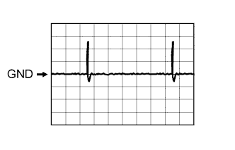
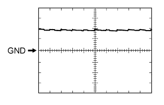
Using an oscilloscope, check waveform 1.
Tech Tips
The oscilloscope waveform shown in the illustration is an example for reference only. Noise, chattering, etc. are not shown.
Waveform 1 (Reference) Item Content Tester Connection
-
I86-5 (CLG1) - I86-1 (E)
-
I86-13 (CLG2) - I86-1 (E)
Tool Setting 2 V/DIV., 500 ms/DIV. Condition Procedure:
-
Power switch off
-
Electrical key transmitter sub-assembly brought outside vehicle
-
All doors closed
-
Electrical key transmitter sub-assembly not inside vehicle
-
Electrical key transmitter sub-assembly brought inside detection area*
-
All doors locked through wireless operation
-
*: For details about the areas that are inside the entry function detection area, refer to Operation Check Click here.
-
-
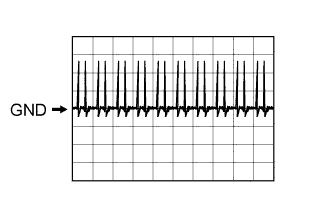
Using an oscilloscope, check waveform 2.
Tech Tips
The oscilloscope waveform shown in the illustration is an example for reference only. Noise, chattering, etc. are not shown.
Waveform 2 (Reference) Item Content Tester Connection
-
I86-5 (CLG1) - I86-1 (E)
-
I86-13 (CLG2) - I86-1 (E)
Tool Setting 2 V/DIV., 500 ms/DIV. Condition Procedure:
-
Power switch off
-
Electrical key transmitter sub-assembly brought outside vehicle
-
All doors closed
-
Electrical key transmitter sub-assembly not inside vehicle
-
Electrical key transmitter sub-assembly brought outside detection area*
-
All doors locked through wireless operation
-
*: For details about the areas that are outside the entry function detection area, refer to Operation Check Click here.
Waveform 2 (Reference) Item Content Tester Connection
-
I86-4 (CG1B) - I86-1 (E)
-
I86-12 (CG2B) - I86-1 (E)
Tool Setting 2 V/DIV., 500 ms/DIV. Condition Procedure:
-
Power switch off
-
Electrical key transmitter sub-assembly brought outside vehicle
-
All doors closed
-
Electrical key transmitter sub-assembly not inside vehicle
-
All doors locked through wireless operation
-
*: For details about the areas that are outside the entry function detection area, refer to Operation Check Click here.
-
-
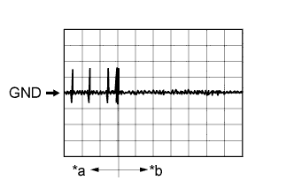
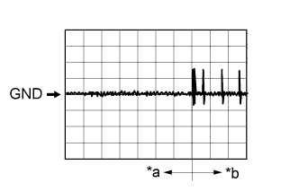
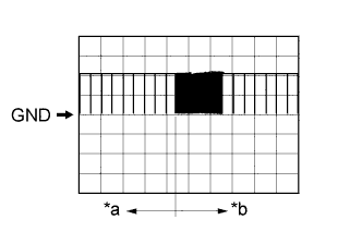
Text in Illustration *a Door open *b After approximately 30 seconds from when the door is closed Using an oscilloscope, check waveform 3.
Tech Tips
The oscilloscope waveform shown in the illustration is an example for reference only. Noise, chattering, etc. are not shown.
Waveform 3 (Reference) Item Content Tester Connection
-
I86-11 (CLG5) - I86-1 (E)
-
I86-10 (CG5B) - I86-1 (E)
-
O2-14 (CLG6) - I86-1 (E)
-
O2-5 (CG6B) - I86-1 (E)
Tool Setting 2 V/DIV., 500 ms/DIV. Condition Procedure:
-
Power switch off
-
Electrical key transmitter sub-assembly not inside vehicle
-
Door is open
-
Door is closed
-
Within 30 seconds
-
-
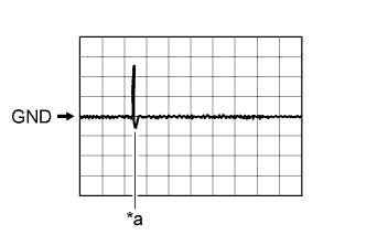
Text in Illustration *a Before driver door lock sensor touched *b After driver door lock sensor touched Using an oscilloscope, check waveform 4.
Tech Tips
The oscilloscope waveform shown in the illustration is an example for reference only. Noise, chattering, etc. are not shown.
Waveform 4 (Reference) Item Content Tester Connection
-
O2-4 (CLG7) - I86-1 (E)
-
O2-3 (CG7B) - I86-1 (E)
Tool Setting 2 V/DIV., 500 ms/DIV. Condition Proceed:
-
Power switch off
-
Electrical key transmitter sub-assembly not inside vehicle
-
All doors closed
-
Driver door lock sensor not touched → touched
-
-
Text in Illustration *a Power switch off, all doors closed and luggage door opening switch assembly off → on Using an oscilloscope, check waveform 5.
Tech Tips
The oscilloscope waveform shown in the illustration is an example for reference only. Noise, chattering, etc. are not shown.
Waveform 5 (Reference) Item Content Tester Connection
-
O2-2 (CLG8) - I86-1 (E)
-
O2-1 (CG8B) - I86-1 (E)
Tool Setting 2 V/DIV., 500 ms/DIV. Condition Procedure:
-
Power switch off
-
Electrical key transmitter sub-assembly brought outside vehicle
-
All doors closed
-
Luggage door opening switch assembly off → on
-
-
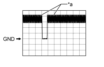
Text in Illustration *a In actuality, sampling is being performed Using an oscilloscope, check waveform 6.
Tech Tips
The oscilloscope waveform shown in the illustration is an example for reference only. Noise, chattering, etc. are not shown.
Waveform 6 (Reference) Item Content Tester Connection I87-7 (TSW1) - I86-1 (E) Tool Setting 2 V/DIV., 500 ms/DIV. Condition Procedure:
-
Power switch off
-
Electrical key transmitter sub-assembly brought outside vehicle
-
All doors closed
-
Driver door lock sensor not touched → touched
Waveform 6 (Reference) Item Content Tester Connection I87-8 (TSW2) - I86-1 (E) Tool Setting 2 V/DIV., 500 ms/DIV. Condition Procedure:
-
Power switch off
-
Electrical key transmitter sub-assembly brought outside vehicle
-
All doors closed
-
Front passenger door lock sensor not touched → touched
Waveform 6 (Reference) Item Content Tester Connection I86-3 (SEN1) - I86-1 (E) Tool Setting 2 V/DIV., 500 ms/DIV Condition Procedure:
-
Power switch off
-
Electrical key transmitter sub-assembly brought outside vehicle
-
All doors locked
-
Electrical key transmitter sub-assembly not sufficiently close to vehicle
-
Driver door unlock sensor not touched → touched
Waveform 6 (Reference) Item Content Tester Connection I86-2 (SEN2) - I86-1 (E) Tool Setting 2 V/DIV., 500 ms/DIV. Condition Procedure:
-
Power switch off
-
Electrical key transmitter sub-assembly brought outside vehicle
-
All doors locked
-
Electrical key transmitter sub-assembly not sufficiently close to vehicle
-
Front passenger door unlock sensor not touched → touched
Waveform 6 (Reference) Item Content Tester Connection O2-22 (TSW5) - I86-1 (E) Tool Setting 2 V/DIV., 500 ms/DIV Condition Luggage door opening switch assembly off → on -
-
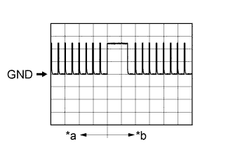
Text in Illustration *a Before lock or unlock button of electrical key transmitter sub-assembly pressed *b After lock or unlock button of electrical key transmitter sub-assembly pressed Using an oscilloscope, check waveform 7.
Tech Tips
The oscilloscope waveform shown in the illustration is an example for reference only. Noise, chattering, etc. are not shown.
Waveform 7 (Reference) Item Content Tester Connection O2-15 (RCO) - I86-1 (E) Tool Setting 2 V/DIV., 500 ms/DIV. Condition Procedure:
-
Power switch off
-
Electrical key transmitter sub-assembly brought outside vehicle
-
Electrical key transmitter sub-assembly brought outside detection area*1 but kept inside wireless function operational area*2
-
Lock or unlock button of electrical key transmitter sub-assembly not pressed → pressed
-
*1: For details about the areas that are outside the entry function detection area, refer to Operation Check Click here.
-
*2: For details about the areas that are inside the wireless function operational area, refer to Operation Check Click here.
-
-
Text in Illustration *a Before lock or unlock button of electrical key transmitter sub-assembly pressed *b After lock or unlock button of electrical key transmitter sub-assembly pressed Using an oscilloscope, check waveform 8.
Tech Tips
The oscilloscope waveform shown in the illustration is an example for reference only. Noise, chattering, etc. are not shown.
Waveform 8 (Reference) Item Content Tester Connection O2-6 (RDAM) - I86-1 (E) Tool Setting 5 V/DIV., 500 ms/DIV. Condition Proceed:
-
Power switch off
-
All doors locked
-
Electrical key transmitter sub-assembly brought outside detection area*1 but kept inside wireless function operational area*2
-
Lock or unlock button of electrical key transmitter sub-assembly not pressed → pressed
-
*1: For details about the areas that are outside the entry function detection area, refer to Operation Check Click here.
-
*2: For details about the areas that are inside the wireless function operational area, refer to Operation Check Click here.
-
-
-
CHECK POWER MANAGEMENT CONTROL ECU
-
Disconnect the A39, I3 and I4 connectors.
-
Measure the voltage and resistance according to the value(s) in the table below.
Tester Connection Wiring Color Terminal Description Condition Specified Condition A39-2 (IG2D) - Body ground R - Body ground IG2 relay operation signal Always 131 to 230 Ω I4-10(STP) - Body ground W - Body ground Stop light switch signal Brake pedal depressed 11 to 14 V I4-10(STP) - Body ground W - Body ground Stop light switch signal Brake pedal released Below 1 V I3-1 (AM22) - Body ground SB - Body ground +B power supply Always 11 to 14 V I4-7 (AM21) - Body ground L - Body ground +B power supply Always 11 to 14 V I4-12 (SLP) - Body ground P - Body ground Steering lock actuator assembly position signal Always 10 kΩ or higher I3-6 (E1) - Body ground BR - Body ground Ground Always Below 1 Ω I4-4 (E12) - Body ground BR - Body ground Ground Power switch not pushed 10 kΩ or higher I4-17 (SSW2) - Body ground V - Body ground Power switch signal Power switch pushed Below 1 Ω I4-17 (SSW2) - Body ground V - Body ground Power switch signal Power switch not pushed 10 kΩ or higher I3-7 (SSW1) - Body ground R - Body ground Power switch signal Power switch pushed Below 1 Ω I4-2 (IG1D) - Body ground P - Body ground IG1 relay operation signal Always 50.625 to 61.875 Ω If the result is not as specified, there may be a malfunction in the wire harness.
-
Reconnect the A39, I3 and I4 connectors.
-
Measure the voltage and check pulses according to the value(s) in the table below.
Tester Connection Wiring Color Terminal Description Condition Specified Condition A39-2 (IG2D) - I3-6 (E1) R - BR IG2 signal Power switch on (IG) Output voltage at terminal AM21 or AM22 is -2 V or more A39-2 (IG2D) - I3-6 (E1) R - BR IG2 signal Power switch on (ACC) Below 1 V I4-12 (SLP) - I3-6 (E1) P - BR Steering lock actuator assembly signal Steering lock released Below 1.2 V I4-12 (SLP) - I3-6 (E1) P - BR Steering lock actuator assembly signal Shift lever in P
Steering lock locked
11 to 14 V I4-14 (P2) - I3-6 (E1) R - BR Shift lock signal Shift lever in P 9 V or higher I4-14 (P2) - I3-6 (E1) R - BR Shift lock signal Shift lever not in P Below 1.5 V I4-17 (SSW2) - I3-6 (E1) V - BR Power switch signal Power switch not pushed Output voltage at terminal AM21 or AM22 is -2 V or more I4-17 (SSW2) - I3-6 (E1) V - BR Power switch signal Power switch pushed Below 1 V I3-7 (SSW1) - I3-6 (E1) R - BR Power switch signal Power switch not pushed Output voltage at terminal AM21 or AM22 is -2 V or more I3-7 (SSW1) - I3-6 (E1) R - BR Power switch signal Power switch pushed Below 1 V I4-1 (ACCD) - I3-6 (E1) W - BR ACC signal Power switch on (ACC) 8 to 14 V I4-1 (ACCD) - I3-6 (E1) W - BR ACC signal Power switch off Below 1 V I4-2 (IG1D) - I3-6 (E1) P - BR IG1 signal Power switch on (IG) 8 to 14 V I4-2 (IG1D) - I3-6 (E1) P - BR IG1 signal Power switch on (ACC) Below 1 V I3-16 (SPDI) - I3-6 (E1) V - BR Vehicle speed signal Driving at approx. 20 km/h (12 mph) Pulse generation
(See waveform 1)
If the result is not as specified, the ECU may be malfunctioning.
-
Using an oscilloscope, check the signal waveform of the ECU.
-
Waveform 1
Tester Connection I3-16 (SPDI) - I3-6 (E1) Tool Setting 5 V/DIV., 10 ms./DIV. Vehicle Condition Driving at approx. 20 km/h (12 mph) Tech Tips
The wavelength becomes shorter as the vehicle speed increases.
-
-
-
CHECK INSTRUMENT PANEL JUNCTION BLOCK ASSEMBLY AND MAIN BODY ECU (MULTIPLEX NETWORK BODY ECU)
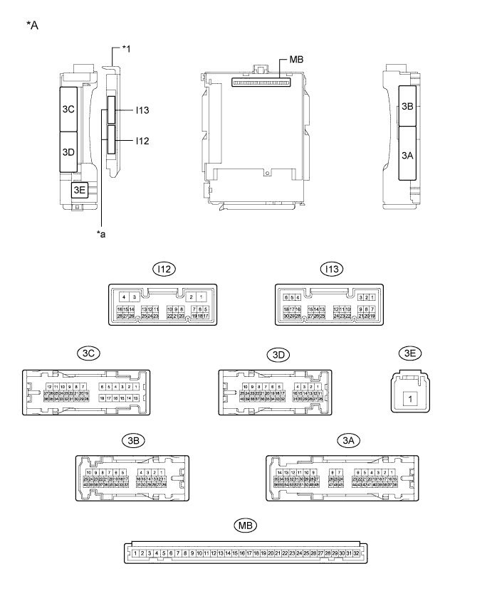
Text in Illustration *A Main Body ECU (Multiplex Network Body ECU) with 2 connectors - - *a 2 connectors - - 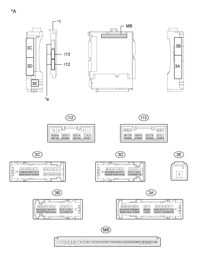
Text in Illustration *A Main Body ECU (Multiplex Network Body ECU) with 3 connectors - - *a 3 connectors - -
-
Remove the main body ECU (multiplex network body ECU) from the instrument panel junction block assembly.
-
Measure the voltage and resistance according to the value(s) in the table below.
Tech Tips
Measure the values on the wire harness side with the connector disconnected.
Tester Connection Input/Output Wiring Color Terminal Description Condition Specified Condition Related Data List Item MB-11 (GND1) - Body ground - - Ground Always Below 1 Ω - I12-3 (GND2) - Body ground - W-B - Body ground Ground Always Below 1 Ω - MB-30 (BECU) - Body ground Input - Auxiliary battery power supply (for CPU) Always 11 to 14 V - MB-31 (ALTB) - Body ground Input - Auxiliary battery power supply (for indicator) Always 11 to 14 V - MB-29 (ACC) - Body ground Input - ACC power supply Power switch on (ACC) 11 to 14 V ACC SW MB-32 (IG) - Body ground Input - Power switch power supply Power switch on (IG) 11 to 14 V IG SW If the result is not as specified, there may be a malfunction in the wire harness.
-
Install the main body ECU (multiplex network body ECU) to the instrument panel junction block assembly.
-
Measure the voltage according to the value(s) in the table below.
Tester Connection Input/Output Wiring Color Terminal Description Condition Specified Condition Related Data List Item 3C-15 (FLCY) - Body ground Input L - Body ground Front door LH courtesy light switch input Front door LH open Below 1 V FL Door Courtesy Front door LH closed Pulse generation (See waveform 1 or 2) I13-19 (FRCY) - Body ground Input SB - Body ground Front door RH courtesy light switch input Front door RH open Below 1 V FR Door Courtesy Front door RH closed Pulse generation (See waveform 3 or 4) I13-1 (LCTY) - Body ground Input P - Body ground Rear door LH courtesy light switch input Rear door LH open Below 1 V RL Door Courtesy Rear door LH closed Pulse generation (See waveform 3 or 4) I13-6 (RCTY) - Body ground Input B - Body ground Rear door RH courtesy light switch input Rear door RH open Below 1 V RR Door Courtesy Rear door RH closed Pulse generation (See waveform 1 or 2) 3C-9 (LGCY) - Body ground Input W - Body ground Luggage door courtesy light switch input Luggage compartment door open Below 1 V Luggage Courtesy SW Power switch off, all doors closed and luggage compartment door closed Pulse generation (See waveform 1 or 2) I13-11 (L2) - Body ground Input R - Body ground Driver door key-linked lock input Driver door key cylinder in lock position Below 1 V Door Key SW-Lock Power switch off, all doors closed and driver door key cylinder in neutral position Pulse generation (See waveform 3 or 4) I13-24 (UL3) - Body ground Input GR - Body ground Driver door key-linked unlock input Driver door key cylinder in unlock position Below 1 V D Door Key SW-UL Power switch off, all doors closed and driver door key cylinder in neutral position Pulse generation (See waveform 1 or 2) 3B-3 (ACT+) - Body ground Output W - Body ground Door lock motor lock drive output Driver door control switch not pushed and driver door key cylinder in neutral position Below 1 V - Lock side of driver door control switch pushed or driver door key cylinder in lock position 11 to 14 V 3B-2 (ACT+) - Body ground Output B - Body ground Door lock motor lock drive output Driver door control switch not pushed and driver door key cylinder in neutral position Below 1 V - Lock side of driver door control switch pushed or driver door key cylinder in lock position 11 to 14 V 3B-1 (ACT+) - Body ground Output L - Body ground Door lock motor lock drive output Driver door control switch not pushed and driver door key cylinder in neutral position Below 1 V - Lock side of driver door control switch pushed or driver door key cylinder in lock position 11 to 14 V 3C-12 (ACT+) - Body ground Output L - Body ground Door lock motor lock drive output Driver door control switch not pushed and driver door key cylinder in neutral position Below 1 V - Lock side of driver door control switch pushed or driver door key cylinder in lock position 11 to 14 V 3B-4 (ACTD) - Body ground Output GR - Body ground Driver door lock motor unlock drive output Driver door control switch not pushed and driver door key cylinder in neutral position Below 1 V - Unlock side of driver door control switch pushed or driver door key cylinder in unlock position 11 to 14 V 3C-10 (TR+) - Body ground Output R - Body ground Driver door lock motor unlock drive output Luggage door open button of electrical key transmitter sub-assembly not pressed Below 1 V - Luggage door open button of electrical key transmitter sub-assembly pressed 11 to 14 V 3B-8 (ACT-) - Body ground Output V - Body ground Door lock motor unlock drive output Driver door control switch not pushed and driver door key cylinder in neutral position Below 1 V - Unlock side of driver door control switch pushed or driver door key cylinder in unlock position 11 to 14 V 3C-11 (ACT-) - Body ground Output G - Body ground Door lock motor unlock drive output Driver door control switch not pushed and driver door key cylinder in neutral position Below 1 V - Unlock side of driver door control switch pushed or driver door key cylinder in unlock position 11 to 14 V 3B-9 (ACT-) - Body ground Output B - Body ground Door lock motor unlock drive output Driver door control switch not pushed and driver door key cylinder in neutral position Below 1 V - Unlock side of driver door control switch pushed or driver door key cylinder in unlock position 11 to 14 V I13-7 (LSFL) - Body ground Input V - Body ground Front door LH unlock detection switch input Front door LH unlocked Below 1 V FL Door Lock Pos Power switch off, all doors closed and front door LH locked Pulse generation (See waveform 3 or 4) I13-18 (LSFR) - Body ground Input W - Body ground Front door RH unlock detection switch input Front door RH unlocked Below 1 V FR Door Lock Pos Power switch off, all doors closed and front door RH locked Pulse generation (See waveform 1 or 2) 3C-17 (LSR) - Body ground Input LG - Body ground Rear door LH unlock detection switch input Rear door LH or RH unlocked Below 1 V RL-Door Lock Pos SW Power switch off, all doors closed and rear door LH and RH locked Pulse generation (See waveform 3 or 4) 3A-53 (LSR) - Body ground Input Y - Body ground Rear door RH unlock detection switch input Rear door RH or LH unlocked Below 1 V RR-Door Lock Pos SW Power switch off, all doors closed and rear door RH and LH locked Pulse generation (See waveform 3 or 4) If the result is not as specified, the main body ECU (multiplex network body ECU) or instrument panel junction block assembly may be malfunctioning.
-
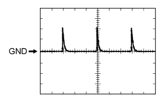
Using an oscilloscope, check waveform 1.
Tech Tips
The oscilloscope waveform shown in the illustration is an example for reference only. Noise, chattering, etc. are not shown.
Waveform 1 (Reference) Item Content Tester Connection 3C-15 (FLCY) - Body ground Tool Setting 5 V/DIV., 20 ms/DIV. Condition Front door LH closed Waveform 1 (Reference) Item Content Tester Connection 3C-9 (LGCY) - Body ground Tool Setting 5 V/DIV., 20 ms/DIV. Condition Power switch off, all doors closed and luggage compartment door closed Waveform 1 (Reference) Item Content Tester Connection I13-6 (RCTY) - Body ground Tool Setting 5 V/DIV., 20 ms/DIV. Condition Rear door RH closed Waveform 1 (Reference) Item Content Tester Connection I13-24 (UL3) - Body ground Tool Setting 5 V/DIV., 20 ms/DIV. Condition Power switch off, all doors closed and driver door key cylinder in neutral position Waveform 1 (Reference) Item Content Tester Connection I13-18 (LSFR) - Body ground Tool Setting 5 V/DIV., 20 ms/DIV. Condition Power switch off, all doors closed and front door RH locked -
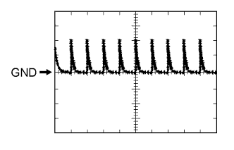
Using an oscilloscope, check waveform 2.
Tech Tips
The oscilloscope waveform shown in the illustration is an example for reference only. Noise, chattering, etc. are not shown.
Waveform 2 (Reference) Item Content Tester Connection 3C-15 (FLCY) - Body ground Tool Setting 5 V/DIV., 20 ms/DIV. Condition Front door LH closed Waveform 2 (Reference) Item Content Tester Connection 3C-9 (LGCY) - Body ground Tool Setting 5 V/DIV., 20 ms/DIV. Condition Power switch off, all doors closed and luggage compartment door closed Waveform 2 (Reference) Item Content Tester Connection I13-6 (RCTY) - Body ground Tool Setting 5 V/DIV., 20 ms/DIV. Condition Rear door RH closed Waveform 2 (Reference) Item Content Tester Connection I13-24 (UL3) - Body ground Tool Setting 5 V/DIV., 20 ms/DIV. Condition Power switch off, all doors closed and driver door key cylinder in neutral position Waveform 2 (Reference) Item Content Tester Connection I13-18 (LSFR) - Body ground Tool Setting 5 V/DIV., 20 ms/DIV. Condition Power switch off, all doors closed and front door RH locked -
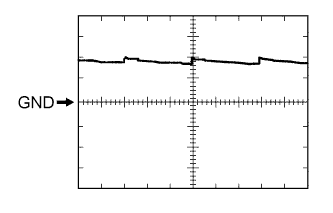
Using an oscilloscope, check waveform 3.
Tech Tips
The oscilloscope waveform shown in the illustration is an example for reference only. Noise, chattering, etc. are not shown.
Waveform 3 (Reference) Item Content Tester Connection I13-1 (LCTY) - Body ground Tool Setting 5 V/DIV., 20 ms/DIV. Condition Rear door LH closed Waveform 3 (Reference) Item Content Tester Connection I13-19 (FRCY) - Body ground Tool Setting 5 V/DIV., 20 ms/DIV. Condition Front door RH closed Waveform 3 (Reference) Item Content Tester Connection I13-11 (L2) - Body ground Tool Setting 5 V/DIV., 20 ms/DIV. Condition Power switch off, all doors closed and driver door key cylinder in neutral position Waveform 3 (Reference) Item Content Tester Connection I13-7 (LSFL) - Body ground Tool Setting 5 V/DIV., 20 ms/DIV. Condition Power switch off, all doors closed and front door LH locked Waveform 3 (Reference) Item Content Tester Connection 3C-17 (LSR) - Body ground Tool Setting 5 V/DIV., 20 ms/DIV. Condition Power switch off, all doors closed and rear door LH and RH locked Waveform 3 (Reference) Item Content Tester Connection 3A-53 (LSR) - Body ground Tool Setting 5 V/DIV., 20 ms/DIV. Condition Power switch off, all doors closed and rear door RH and LH locked -
Using an oscilloscope, check waveform 4.
Tech Tips
The oscilloscope waveform shown in the illustration is an example for reference only. Noise, chattering, etc. are not shown.
Waveform 4 (Reference) Item Content Tester Connection I13-1 (LCTY) - Body ground Tool Setting 5 V/DIV., 20 ms/DIV. Condition Rear door LH closed Waveform 4 (Reference) Item Content Tester Connection I13-19 (FRCY) - Body ground Tool Setting 5 V/DIV., 20 ms/DIV. Condition Front door RH closed Waveform 4 (Reference) Item Content Tester Connection I13-11 (L2) - Body ground Tool Setting 5 V/DIV., 20 ms/DIV. Condition Power switch off, all doors closed and driver door key cylinder in neutral position Waveform 4 (Reference) Item Content Tester Connection I13-7 (LSFL) - Body ground Tool Setting 5 V/DIV., 20 ms/DIV. Condition Power switch off, all doors closed and front door LH locked Waveform 4 (Reference) Item Content Tester Connection 3C-17 (LSR) - Body ground Tool Setting 5 V/DIV., 20 ms/DIV. Condition Power switch off, all doors closed and rear door LH and RH locked Waveform 4 (Reference) Item Content Tester Connection 3A-53 (LSR) - Body ground Tool Setting 5 V/DIV., 20 ms/DIV. Condition Power switch off, all doors closed and rear door RH and LH locked
-