FRONT DOOR LOCK INSTALLATION

Tech Tips
-
Use the same procedure for the LH side and RH side.
-
The following procedure is for the LH side.
-
INSTALL FRONT DOOR INSIDE LOCKING CABLE ASSEMBLY
-
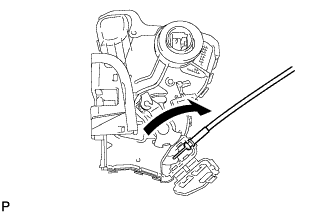
Install the front door inside locking cable assembly.
-
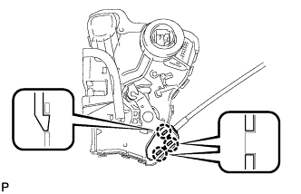
Engage the 3 claws.
-
-
INSTALL FRONT DOOR LOCK REMOTE CONTROL CABLE ASSEMBLY
-
Install the front door lock remote control cable assembly.
-
-
INSTALL FRONT DOOR LOCK WITH MOTOR ASSEMBLY
Note
-
When reusing a removed front door lock with motor assembly, replace the door lock wiring harness seal with a new one.
-
Do not allow grease or dust to adhere to the door lock wiring harness seal installation surface.
-
Reusing a door lock wiring harness seal or using a damaged door lock wiring harness seal may cause water ingress. This may result in a malfunction of the front door lock with motor assembly.
-
Apply MP grease to the sliding parts of the front door lock with motor assembly.
-
When reusing the front door lock with motor assembly.
-
Install a new door lock wiring harness seal to the front door lock with motor assembly.
-
-
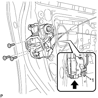
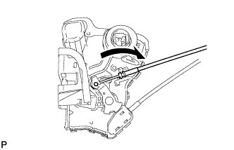
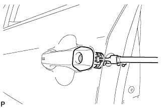
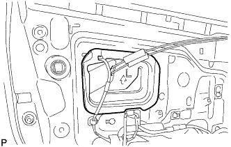
Text in Illustration *1 Front Door Lock Open Rod Connect the front door lock open rod to the front door lock with motor assembly.
Tech Tips
Make sure that the front door lock open rod is securely connected to the front door lock with motor assembly.
-
Using a T30 "TORX" socket wrench, install the front door lock with motor assembly with the 3 screws.
- Torque:
- 5.0 N*m { 51 kgf*cm, 44 in.*lbf }
-
-
INSTALL FRONT DOOR OUTSIDE HANDLE COVER WITH LOCK CYLINDER ASSEMBLY (w/ Lock Cylinder)
-
Using a T30 "TORX" socket wrench, install the front door outside handle cover with lock cylinder assembly with the screw.
- Torque:
- 4.0 N*m { 41 kgf*cm, 35 in.*lbf }
-
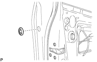
Install the hole plug.
-
-
INSTALL FRONT DOOR REAR LOWER FRAME SUB-ASSEMBLY
-
Engage the guide as shown in the illustration.
-
Install the front door rear lower frame sub-assembly with the 2 bolts.
-
-
INSTALL FRONT DOOR GLASS RUN
-
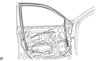
Install the front door glass run.
-
-
INSTALL FRONT DOOR GLASS SUB-ASSEMBLY
-
Connect the cable to the negative (-) auxiliary battery terminal.
-
for Driver Side:
-
Connect the power window regulator master switch assembly and move the front door glass sub-assembly so that the door glass bolts can be seen.
-
Disconnect the power window regulator master switch assembly.
-
-
for Front Passenger Side:
-
Connect the power window regulator switch assembly and move the front door glass sub-assembly so that the door glass bolts can be seen.
-
Disconnect the power window regulator switch assembly.
-
-
Disconnect the cable from the negative (-) auxiliary battery terminal.
CAUTION:
Wait at least 90 seconds after disconnecting the cable from the negative (-) auxiliary battery terminal to disable the SRS system.
Note
When disconnecting the cable, some systems need to be initialized after the cable is reconnected Click here.
-
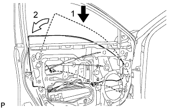
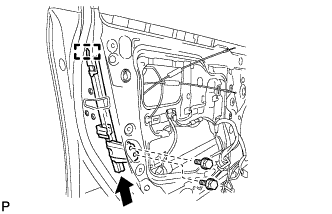
Insert the front door glass sub-assembly into the front door panel along the front door glass run as indicated by the arrows, in the order shown in the illustration.
Note
Do not the damage the front door glass sub-assembly.
-
Install the front door glass sub-assembly with the 2 bolts.
- Torque:
- 8.0 N*m { 82 kgf*cm, 71 in.*lbf }
-
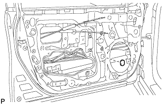
Install the grommet.
-
-
INSTALL NO. 2 FRONT DOOR SERVICE HOLE SEAL
-
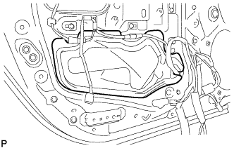
Install the No. 2 front door service hole seal.
-
-
INSTALL NO. 1 FRONT DOOR SERVICE HOLE SEAL
-
Install the No. 1 front door service hole seal.
-
-
INSTALL FRONT DOOR SERVICE HOLE COVER
-
Apply new butyl tape to the front door panel.
-
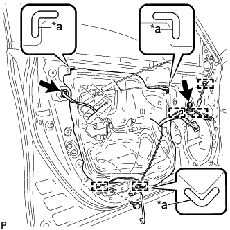
Text in Illustration *a Reference Point Pass the front door lock remote control cable assembly, front door inside locking cable assembly and each connector through a new front door service hole cover.
-
Install the new front door service hole cover according to the reference points on the front door panel.
Note
Securely install the front door service hole cover preventing wrinkles and air bubbles.
-
Engage the 5 clamps.
-
Install the bolt.
- Torque:
- 8.0 N*m { 82 kgf*cm, 71 in.*lbf }
-
Connect each connector.
-
-
INSTALL DOOR SIDE AIRBAG SENSOR
-
Check that the power switch is off.
-
Check that the cable is disconnected from the negative (-) auxiliary battery terminal.
CAUTION:
Wait at least 90 seconds after disconnecting the cable from the negative (-) auxiliary battery terminal to disable the SRS system.
-
Before connecting the connector, check that the position of the white housing lock is correct as shown in the illustration.
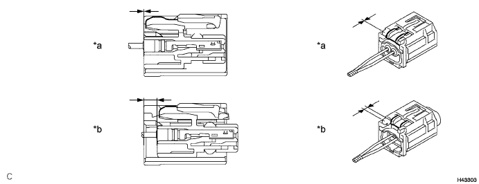
Text in Illustration *a Incorrect *b Correct -
Insert the pin (stopper) into the door hole and install the door side airbag sensor to the front door panel with the bolt.
- Torque:
- 9.0 N*m { 92 kgf*cm, 80 in.*lbf }
Note
-
If the door side airbag sensor has been dropped, or there are any cracks, dents or other defects in the case or connector, replace it with a new one.
-
When installing the door side airbag sensor, be careful that the SRS wiring does not interfere with or is not pinched between other parts.
-
Make sure that the pin (stopper) is securely inserted into the door hole.
-
Tighten the bolt while holding the door side airbag sensor because the door side airbag sensor pin (stopper) is easily damaged.
-
Connect the connector to the door side airbag sensor.
Note
When connecting any airbag connector, take care not to damage the airbag wire harness.
-
Be sure to engage the connectors until they are locked (when locking, make sure that a click sound can be heard).
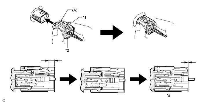
Text in Illustration *1 White Housing Lock *2 Yellow CPA *a Connection is Completed - - Tech Tips
When engaged, the white housing lock will slide. Be sure not to hold the white housing lock or part (A), as it may result in an insecure fit.
-
-
Check that there is no looseness in the installation parts of the door side airbag sensor.
-
-
INSTALL FRONT DOOR INNER GLASS WEATHERSTRIP
-
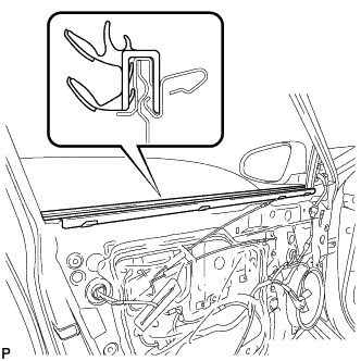
Install the front door inner glass weatherstrip.
-
-
INSTALL FRONT DOOR TRIM BOARD SUB-ASSEMBLY
-
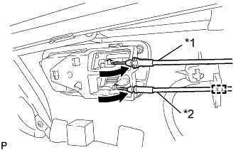
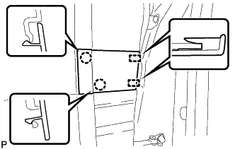
Text in Illustration *1 Front Door Inside Locking Cable Assembly *2 Front Door Lock Remote Control Cable Assembly Connect the front door lock remote control cable assembly and front door inside locking cable assembly.
-
Engage the clamp.
-
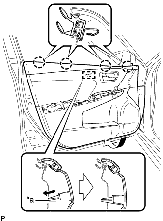
Text in Illustration *a Reference Boss Engage the 4 claws and reference boss as shown in the illustration.
-
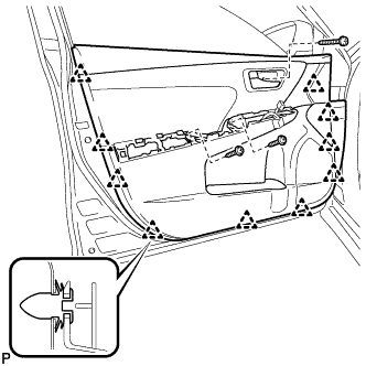
Engage the 10 clips to install the front door trim board sub-assembly.
-
Install the 3 screws.
-
Remove protective tape.
-
-
INSTALL COURTESY LIGHT ASSEMBLY
-
Connect the connector.
-
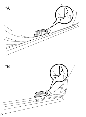
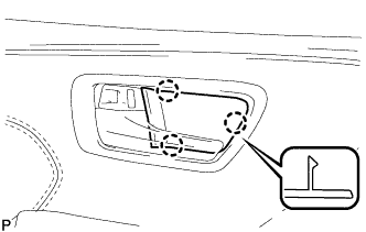
Text in Illustration *A for LH Side *B for RH Side Engage the claw to install the courtesy light assembly.
-
-
INSTALL FRONT ARMREST ASSEMBLY
-
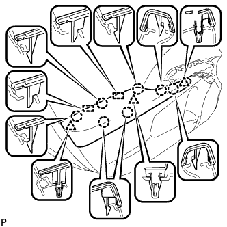
Engage the 2 guides, 3 clips and 7 claws to install the front armrest assembly.
-
-
INSTALL POWER WINDOW REGULATOR MASTER SWITCH ASSEMBLY WITH FRONT DOOR ARMREST BASE PANEL (for Driver Side)
-
Connect each connector.
-
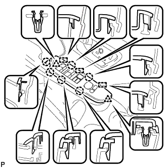
Engage the 3 guides, 2 clips and 6 claws to install the power window regulator master switch assembly with front door armrest base panel.
-
-
INSTALL POWER WINDOW REGULATOR SWITCH ASSEMBLY WITH FRONT DOOR ARMREST BASE PANEL (for Front Passenger Side)
-
Connect each connector.
-
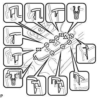
Engage the 3 guides, 2 clips and 6 claws to install the power window regulator switch assembly with front door armrest base panel.
-
-
INSTALL FRONT DOOR FRONT LOWER FRAME UPPER COVER
-
Engage the 2 guides and 2 claws to install the front door front lower frame upper cover.
-
-
INSTALL FRONT DOOR INSIDE HANDLE BEZEL PLUG
-
Engage the 3 claws to install the front door inside handle bezel plug.
-
-
CONNECT CABLE TO NEGATIVE AUXILIARY BATTERY TERMINAL
Note
When disconnecting the cable, some systems need to be initialized after the cable is reconnected Click here.
-
INSTALL LUGGAGE TRIM SERVICE HOLE COVER
-
Engage the claw to connect the luggage trim service hole cover.
-
-
INITIALIZE POWER WINDOW CONTROL SYSTEM
-
CHECK POWER WINDOW CONTROL SYSTEM
-
INSPECT SRS WARNING LIGHT