FRONT DOOR LOCK REMOVAL

Tech Tips
-
Use the same procedure for the LH side and RH side.
-
The following procedure is for the LH side.
-
PRECAUTION
Note
After turning the power switch off, waiting time may be required before disconnecting the cable from the negative (-) auxiliary battery terminal. Therefore, make sure to read the disconnecting the cable from the negative (-) auxiliary battery terminal notices before proceeding with work Click here.
-
REMOVE LUGGAGE TRIM SERVICE HOLE COVER
-
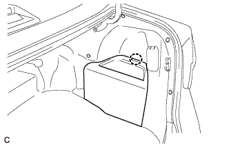
Disengage the claw to remove the luggage trim service hole cover.
-
-
DISCONNECT CABLE FROM NEGATIVE AUXILIARY BATTERY TERMINAL
CAUTION:
Wait at least 90 seconds after disconnecting the cable from the negative (-) auxiliary battery terminal to disable the SRS system.
Note
When disconnecting the cable, some systems need to be initialized after the cable is reconnected Click here.
-
REMOVE FRONT DOOR INSIDE HANDLE BEZEL PLUG
-
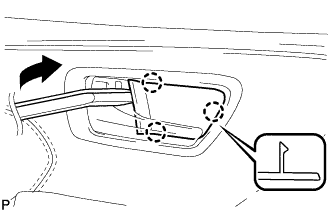
Using a moulding remover, disengage the 3 claws and remove the front door inside handle bezel plug as shown in the illustration.
-
-
REMOVE FRONT DOOR FRONT LOWER FRAME UPPER COVER
-
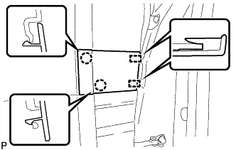
Disengage the 2 claws and 2 guides and remove the front door front lower frame upper cover.
-
-
REMOVE POWER WINDOW REGULATOR MASTER SWITCH ASSEMBLY WITH FRONT DOOR ARMREST BASE PANEL (for Driver Side)
-
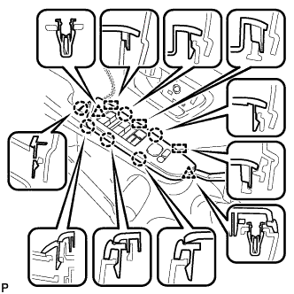
Using a moulding remover, disengage the 2 clips, 6 claws and 3 guides as shown in the illustration.
-
Disconnect each connector and remove the power window regulator master switch assembly with front door armrest base panel.
-
-
REMOVE POWER WINDOW REGULATOR SWITCH ASSEMBLY WITH FRONT DOOR ARMREST BASE PANEL (for Front Passenger Side)
-
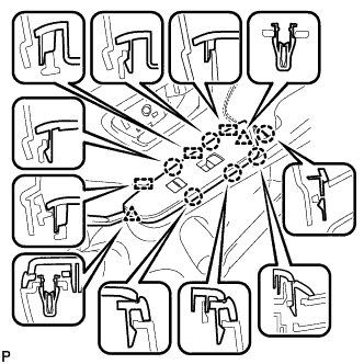
Using a moulding remover, disengage the 2 clips, 6 claws and 3 guides as shown in the illustration.
-
Disconnect each connector and remove the power window regulator switch assembly with front door armrest base panel.
-
-
REMOVE FRONT ARMREST ASSEMBLY
-
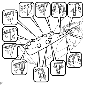
Using a moulding remover, disengage the 3 clips, 7 claws and 2 guides and remove the front armrest assembly.
-
-
REMOVE COURTESY LIGHT ASSEMBLY
-
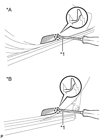
Text in Illustration *A for LH Side *B for RH Side *1 Protective Tape Using a screwdriver with its tip wrapped with protective tape, disengage the claw.
-
Disconnect the connector and remove the courtesy light assembly.
-
-
REMOVE FRONT DOOR TRIM BOARD SUB-ASSEMBLY
-
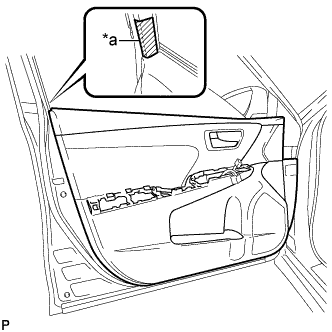
Text in Illustration *a Protective Tape Apply protective tape to the front door panel.
-
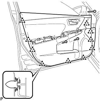
Remove the 3 screws.
-
Using a clip remover, disengage the 10 clips.
-
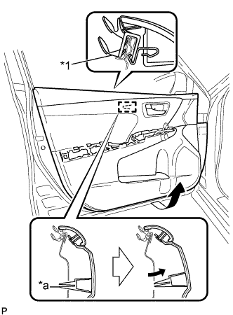
Text in Illustration *1 Front Door Inner Glass Weatherstrip *a Reference Boss Pull out the front door trim board sub-assembly in the direction indicated by the arrow as shown in the illustration.
-
Disengage the reference boss from the front door panel.
-
Raise the front door trim board sub-assembly to remove the front door trim board sub-assembly together with the front door inner glass weatherstrip.
-
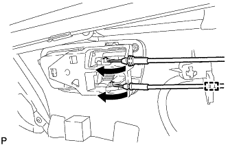
Disengage the clamp.
-
Disconnect the front door lock remote control cable assembly and front door inside locking cable assembly.
-
-
REMOVE FRONT DOOR INNER GLASS WEATHERSTRIP
-
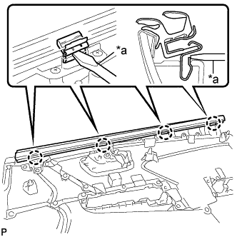
Text in Illustration *a Screwdriver Using a screwdriver, disengage the 4 claws and remove the front door inner glass weatherstrip from the front door trim board sub-assembly as shown in the illustration.
-
-
REMOVE DOOR SIDE AIRBAG SENSOR
-
Check that the power switch is off.
-
Check that the cable is disconnected from the negative (-) auxiliary battery terminal.
CAUTION:
Wait at least 90 seconds after disconnecting the cable from the negative (-) auxiliary battery terminal to disable the SRS system.
-
Disconnect the connector from the door side airbag sensor.
Note
When disconnecting any airbag connector, take care not to damage the airbag wire harness.
-
Push down the white housing lock and slide the yellow CPA. (At this time, the connector cannot be disconnected yet.)
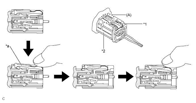
Text in Illustration *1 White Housing Lock *2 Yellow CPA *a Connector Lock is Released - - -
Push down the white housing lock again and disconnect the connector.
Note
Do not push down the part (A) shown in the illustration when disconnecting the connector.
-
-
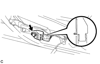
Remove the bolt and door side airbag sensor from the front door panel.
Note
Loosen the bolt while holding the door side airbag sensor because the door side airbag sensor pin (stopper) is easily damaged.
-
After disconnecting the connector, check that the position of the white housing lock is correct as shown in the illustration.
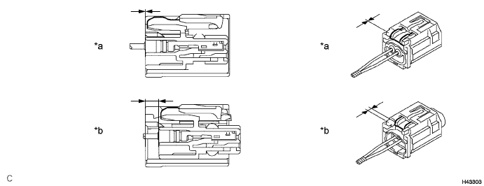
Text in Illustration *a Incorrect *b Correct
-
-
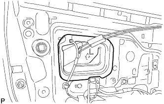
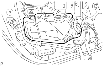
REMOVE FRONT DOOR SERVICE HOLE COVER
-
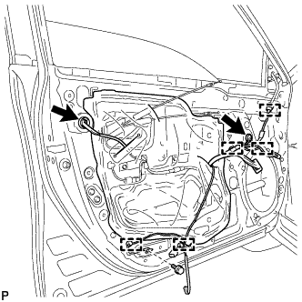
Remove the bolt.
-
Disconnect each connector.
-
Disengage the 5 clamps.
-
Pass the front door lock remote control cable assembly, front door inside locking cable assembly and each connector through the front door service hole cover.
-
Remove the front door service hole cover.
Tech Tips
Remove any remaining butyl tape from the front door panel.
-
-
REMOVE NO. 1 FRONT DOOR SERVICE HOLE SEAL
-
Remove the No. 1 front door service hole seal.
-
-
REMOVE NO. 2 FRONT DOOR SERVICE HOLE SEAL
-
Remove the No. 2 front door service hole seal.
-
-
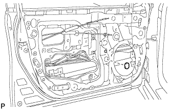
REMOVE FRONT DOOR GLASS SUB-ASSEMBLY
-
Remove the grommet.
-
Connect the cable to the negative (-) auxiliary battery terminal.
-
for Driver Side:
-
Connect the power window regulator master switch assembly and move the front door glass sub-assembly so that the door glass bolts can be seen.
-
Disconnect the power window regulator master switch assembly.
-
-
for Front Passenger Side:
-
Connect the power window regulator switch assembly and move the front door glass sub-assembly so that the door glass bolts can be seen.
-
Disconnect the power window regulator switch assembly.
-
-
Disconnect the cable from the negative (-) auxiliary battery terminal.
CAUTION:
Wait at least 90 seconds after disconnecting the cable from the negative (-) auxiliary battery terminal to disable the SRS system.
Note
When disconnecting the cable, some systems need to be initialized after the cable is reconnected Click here.
-
Remove the 2 bolts.
Note
After the bolts are removed, do not allow the front door glass sub-assembly to fall.
-
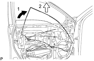
Remove the front door glass sub-assembly as indicated by the arrows, in the order shown in the illustration.
Note
Do not damage the front door glass sub-assembly.
-
-
REMOVE FRONT DOOR GLASS RUN
-
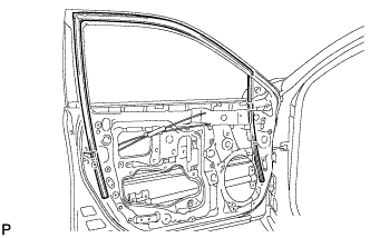
Remove the front door glass run.
-
-
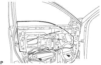
REMOVE FRONT DOOR REAR LOWER FRAME SUB-ASSEMBLY
-
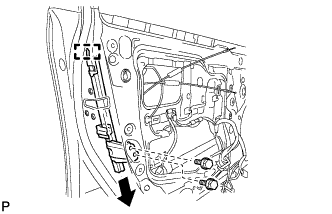
Remove the 2 bolts.
-
Disengage the guide and remove the front door rear lower frame sub-assembly as shown in the illustration.
-
-
REMOVE FRONT DOOR OUTSIDE HANDLE COVER WITH LOCK CYLINDER ASSEMBLY (w/ Lock Cylinder)
-
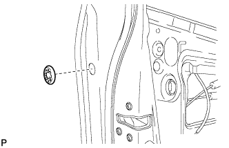
Remove the hole plug.
-
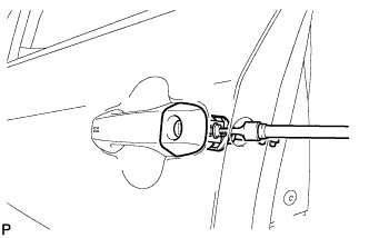
Using a T30 "TORX" socket wrench, loosen the screw and remove the front door outside handle cover with lock cylinder assembly.
Tech Tips
The screw cannot be removed because it is integrated into the front door outside handle frame sub-assembly.
-
-
REMOVE FRONT DOOR LOCK WITH MOTOR ASSEMBLY
-
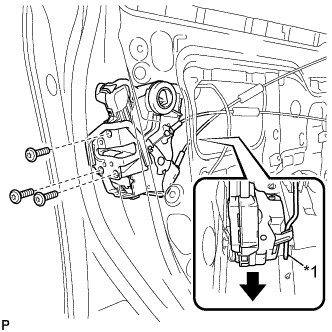
Text in Illustration *1 Front Door Lock Open Rod Using a T30 "TORX" socket wrench, remove the 3 screws.
-
Slide the front door lock with motor assembly downward to disconnect the front door lock open rod and remove the front door lock with motor assembly and cables as a unit.
-
When reusing the front door lock with motor assembly.
-
Remove the door lock wiring harness seal from the front door lock with motor assembly.
-
-
-
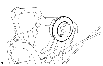
REMOVE FRONT DOOR LOCK REMOTE CONTROL CABLE ASSEMBLY
-
Remove the front door lock remote control cable assembly.
-
-
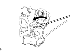
REMOVE FRONT DOOR INSIDE LOCKING CABLE ASSEMBLY
-
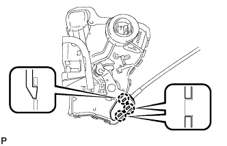
Using a screwdriver, disengage the 3 claws.
-
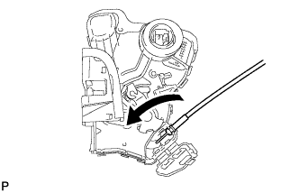
Remove the front door inside locking cable assembly.
-