CAN COMMUNICATION SYSTEM SYSTEM DIAGRAM

-
OVERALL CAN BUS DIAGRAM
-
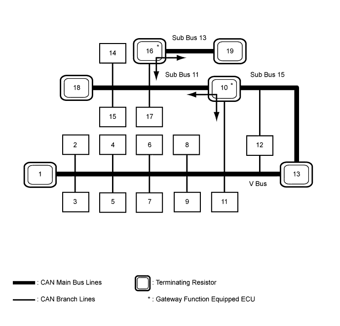
The CAN communication system is composed of 4 buses.
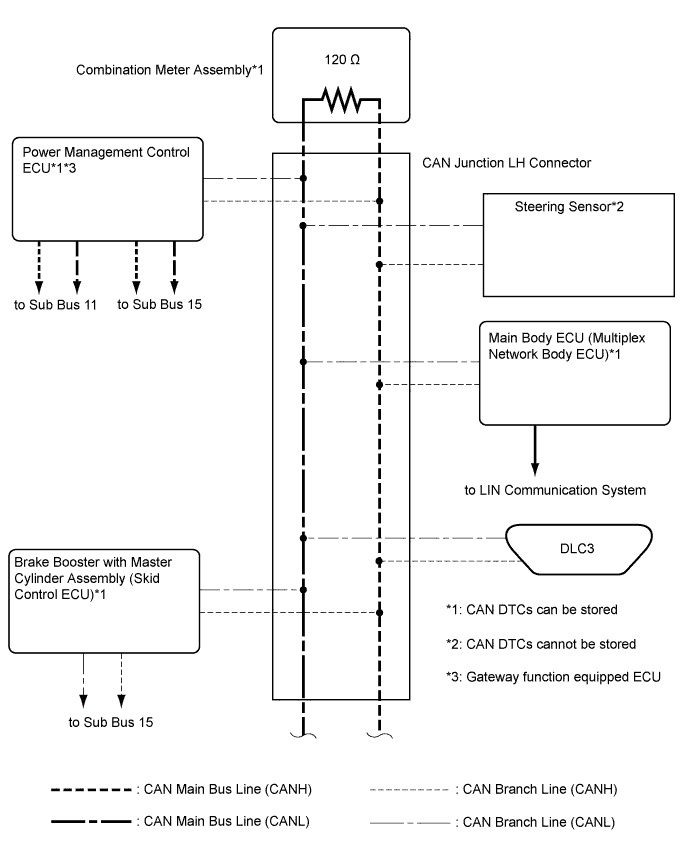
Text in Illustration *1 Combination Meter Assembly
(for V Bus)
*2 Steering Sensor
(for V Bus)
*3 Main Body ECU (Multiplex Network Body ECU)
(for V Bus)
*4 DLC3
(for V Bus)
*5
-
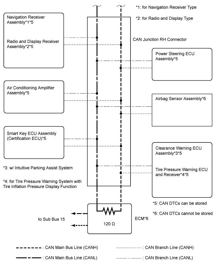
Navigation Receiver Assembly (for Navigation Receiver Type)
-
Radio and Display Receiver Assembly (for Radio and Display Type)
(for V Bus)
*6 Air Conditioning Amplifier Assembly
(for V Bus)
*7 Smart Key ECU Assembly (Certification ECU)
(for V Bus)
*8 Power Steering ECU Assembly
(for V Bus)
*9 Airbag Sensor Assembly
(for V Bus)
*10 Power Management Control ECU
(for V Bus, Sub Bus 11 and Sub Bus 15)
*11
-
Clearance Warning ECU Assembly (w/ Intuitive Parking Assist System)
-
Tire Pressure Warning ECU and Receiver (for Tire Pressure Warning System with Tire Inflation Pressure Display Function)
(for V Bus)
*12 Brake Booster with Master Cylinder Assembly (Skid Control ECU)
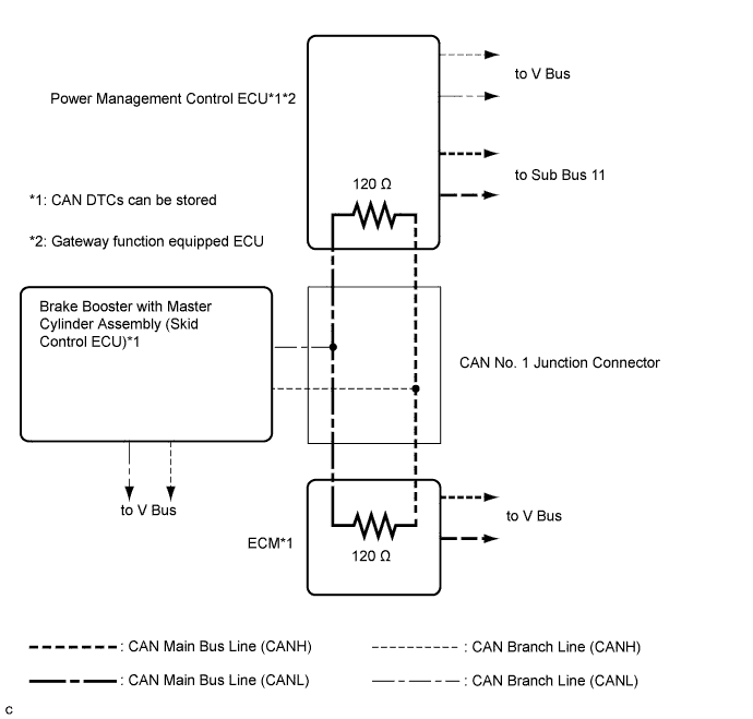
(for V Bus and Sub Bus 15)
*13 ECM
(for V Bus and Sub Bus 15)
*14 Rear Television Camera Assembly (w/ Parking Assist Monitor System)
(for Sub Bus 11)
*15 Lane Departure Warning Camera (w/ Pre-collision System)
(for Sub Bus 11)
*16 Driving Support ECU Assembly (w/ Pre-collision System)
(for Sub Bus 11 and Sub Bus 13)
*17 Blind Spot Monitor Sensor RH (w/ Blind Spot Monitor System)
(for Sub Bus 11)
*18 CAN No. 4 Junction Connector
(for Sub Bus 11)
*19 Millimeter Wave Radar Sensor Assembly (w/ Pre-collision System)
(for Sub Bus 13)
- - -
Tech Tips
-
The power management control ECU functions as a gateway between the V bus and sub bus 11.
-
The driving support ECU assembly functions as a gateway between the sub bus 11 and sub bus 13.
-
Refer to the following bus wiring diagrams for details.
-
-
V BUS
Tech Tips
The CAN communication system connects to other network via ECUs that function as a gateway Click here.
-
SUB BUS 11 (w/ Parking Assist Monitor System)
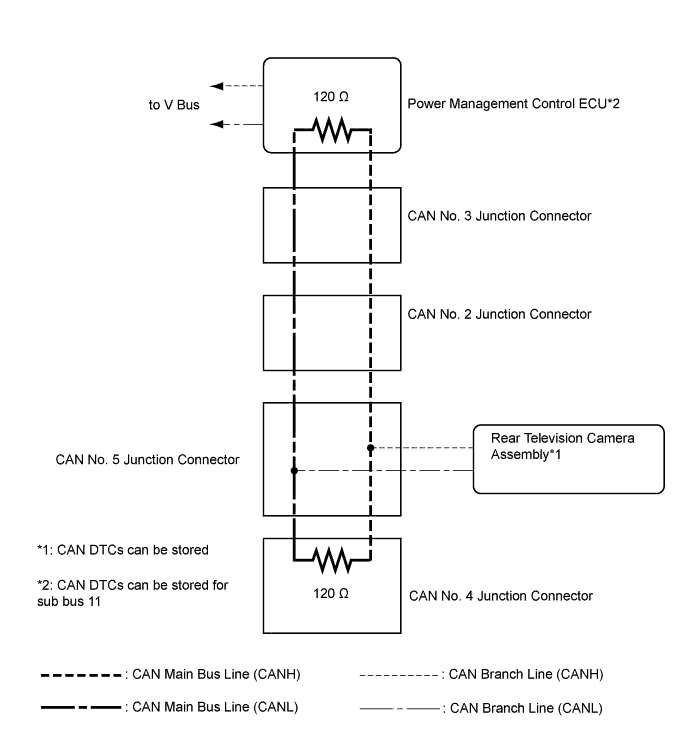
-
SUB BUS 11 (w/o Parking Assist Monitor System)
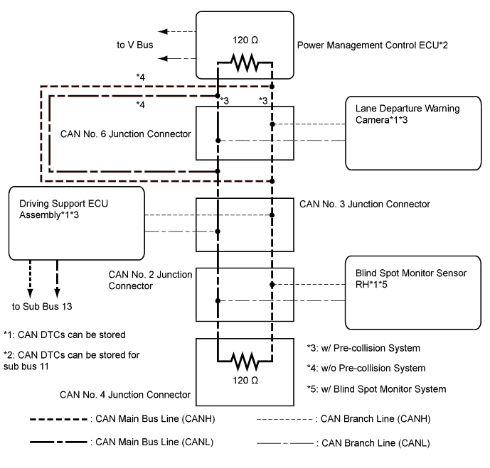
-
SUB BUS 13 (w/ Pre-collision System)
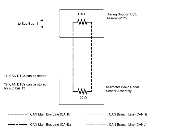
-
SUB BUS 15