LIN COMMUNICATION SYSTEM TERMINALS OF ECU

-
CHECK INSTRUMENT PANEL JUNCTION BLOCK ASSEMBLY AND MAIN BODY ECU (MULTIPLEX NETWORK BODY ECU)
-
Remove the main body ECU (multiplex network body ECU) from the instrument panel junction block assembly.
-
Disconnect the I12 main body ECU (multiplex network body ECU) connector.
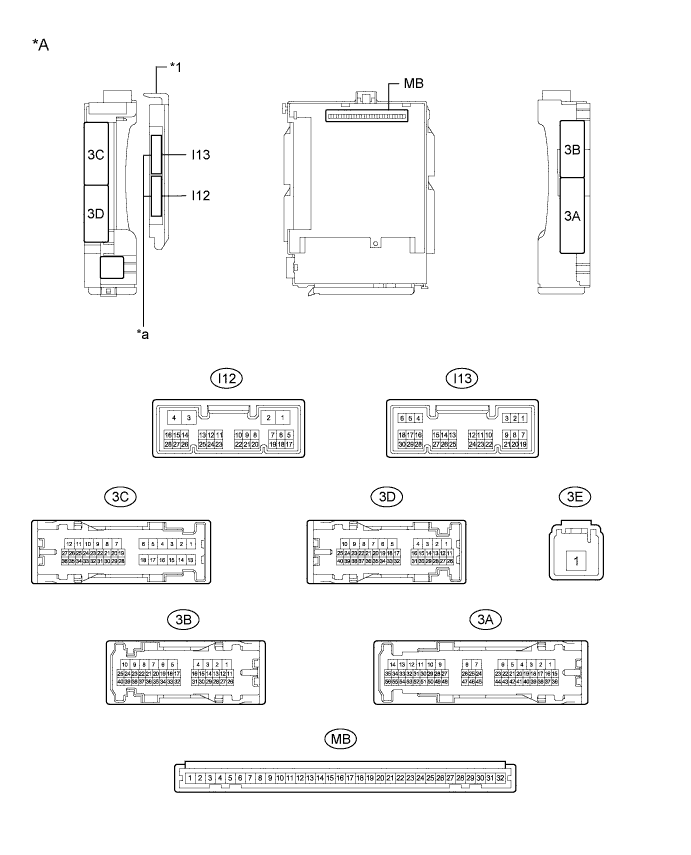
Text in Illustration *A Main Body ECU (Multiplex Network Body ECU) with 2 Connectors - - *1 Main Body ECU (Multiplex Network Body ECU) - - *a 2 Connectors - - 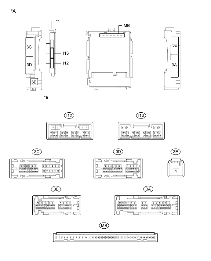
Text in Illustration *A Main Body ECU (Multiplex Network Body ECU) with 3 Connectors - - *1 Main Body ECU (Multiplex Network Body ECU) - - *a 3 Connectors - - -
Measure the voltage and resistance according to the value(s) in the table below.
Tech Tips
Measure the values on the wire harness side with the connectors disconnected.
Tester Connection Wiring Color Terminal Description Condition Specified Condition MB-30 (BECU) - Body ground - Auxiliary battery power supply Power switch off 11 to 14 V MB-11 (GND1) - Body ground - Ground Always Below 1 Ω I12-3 (GND2) - Body ground W-B - Body ground Ground Always Below 1 Ω If the result is not as specified, there may be a malfunction in the wire harness.
-
Reinstall the main body ECU (multiplex network body ECU) to the instrument panel junction block assembly.
-
Reconnect the I12 main body ECU (multiplex network body ECU) connector.
-
Check for pulses according to the value(s) in the table below.
Tester Connection Wiring Color Terminal Description Condition Specified Condition 3B-30 (LIN2) - 3B-7 (GND1) P - W-B LIN communication line Power switch on (IG) Pulse generation If the result is not as specified, the main body ECU (multiplex network body ECU) or instrument panel junction block assembly may be malfunctioning.
-
-
CHECK POWER WINDOW REGULATOR MOTOR ASSEMBLY (for Driver Door)
-
Disconnect the K9 power window regulator motor assembly (for driver Door) connector.

-
Measure the voltage and resistance according to the value(s) in the table below.
Tech Tips
Measure the values on the wire harness side with the connector disconnected.
Tester Connection Wiring Color Terminal Description Condition Specified Condition K9-2 (B) - K9-1 (GND) W - W-B Auxiliary battery power supply Power switch off 11 to 14 V K9-1 (GND) - Body ground W-B - Body ground Ground Always Below 1 Ω If the result is not as specified, there may be a malfunction in the wire harness.
-
Reconnect the K9 power window regulator motor assembly (for driver door) connector.
-
Check for pulses according to the value(s) in the table below.
Tester Connection Wiring Color Terminal Description Condition Specified Condition K9-9 (LIN) - K9-1 (GND) P - W-B LIN communication line Power switch on (IG) Pulse generation If the result is not as specified, the power window regulator motor assembly (for driver door) may be malfunctioning.
-
-
CHECK POWER WINDOW REGULATOR MOTOR ASSEMBLY (for Front Passenger Door)
-
Disconnect the J14 power window regulator motor assembly (for front passenger door) connector.

-
Measure the voltage and resistance according to the value(s) in the table below.
Tech Tips
Measure the values on the wire harness side with the connector disconnected.
Tester Connection Wiring Color Terminal Description Condition Specified Condition J14-2 (B) - J14-1 (GND) GR - W-B Auxiliary battery power supply Power switch off 11 to 14 V J14-1 (GND) - Body ground W-B - Body ground Ground Always Below 1 Ω If the result is not as specified, there may be a malfunction in the wire harness.
-
Reconnect the J14 power window regulator motor assembly (for front passenger door) connector.
-
Check for pulses according to the value(s) in the table below.
Tester Connection Wiring Color Terminal Description Condition Specified Condition J14-9 (LIN) - J14-1 (GND) P - W-B LIN communication line Power switch on (IG) Pulse generation If the result is not as specified, the power window regulator motor assembly (for front passenger door) may be malfunctioning.
-
-
CHECK MULTIPLEX NETWORK MASTER SWITCH ASSEMBLY
-
Disconnect the K11 multiplex network master switch assembly connector.

-
Measure the voltage and resistance according to the value(s) in the table below.
Tech Tips
Measure the values on the wire harness side with the connector disconnected.
Tester Connection Wiring Color Terminal Description Condition Specified Condition K11-3 (B) - K11-1 (GND) R - W-B Auxiliary battery power supply Power switch off 11 to 14 V K11-1 (GND) - Body ground BR - Body ground Ground Always Below 1 Ω If the result is not as specified, there may be a malfunction in the wire harness.
-
Reconnect the K11 multiplex network master switch assembly connector.
-
Check for pulses according to the value(s) in the table below.
Tester Connection Wiring Color Terminal Description Condition Specified Condition K11-6 (LIN1) - K11-1 (GND) P - W-B LIN communication line Power switch on (IG) Pulse generation K11-7 (LIN2) - K11-1 (GND) P - W-B LIN communication line Power switch on (IG) Pulse generation If the result is not as specified, the multiplex network master switch assembly may be malfunctioning.
-
-
CHECK SLIDING ROOF ECU (SLIDING ROOF DRIVE GEAR SUB-ASSEMBLY) (w/ Sliding Roof System)
-
Disconnect the S4 sliding roof ECU (sliding roof drive gear sub-assembly) connector.

-
Measure the voltage and resistance according to the value(s) in the table below.
Tech Tips
Measure the values on the wire harness side with the connector disconnected.
Tester Connection Wiring Color Terminal Description Condition Specified Condition S4-8 (B) - S4-12 (E) B - W-B Auxiliary battery power supply Power switch off 11 to 14 V S4-12 (E) - Body ground W-B - Body ground Ground Always Below 1 Ω If the result is not as specified, there may be a malfunction in the wire harness.
-
Reconnect the S4 sliding roof ECU (sliding roof drive gear sub-assembly) connector.
-
Check for pulses according to the value(s) in the table below.
Tester Connection Wiring Color Terminal Description Condition Specified Condition S4-11 (MPX1) - S4-12 (E) P - W-B LIN communication line Power switch on (IG) Pulse generation If the result is not as specified, the sliding roof ECU (sliding roof drive gear sub-assembly) may be malfunctioning.
-
-
CHECK CERTIFICATION ECU (SMART KEY ECU ASSEMBLY)
-
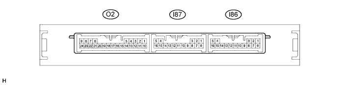
Disconnect the I87 and I86 certification ECU (smart key ECU assembly) connectors.
-
Measure the voltage and resistance according to the value(s) in the table below.
Tech Tips
Measure the values on the wire harness side with the connector disconnected.
Tester Connection Wiring Color Terminal Description Condition Specified Condition I87-5 (+B) - I86-1 (E) SB - W-B Auxiliary battery power supply Power switch off 11 to 14 V I86-1 (E) - Body ground W-B - Body ground Ground Always Below 1 Ω If the result is not as specified, there may be a malfunction in the wire harness.
-
Reconnect the I86 and I87 certification ECU (smart key ECU assembly) connectors.
-
Measure the voltage and check for pulses according to the value(s) in the table below.
Tester Connection Wiring Color Terminal Description Condition Specified Condition I87-16 (IG) - I86-1 (E) LG - W-B IG power supply Power switch on (IG) 11 to 14 V I87-16 (IG) - I86-1 (E) LG - W-B IG power supply Power switch off Below 1 V I87-12 (LIN) - I86-1 (E) Y - W-B LIN communication line Power switch on (IG) Pulse generation If the result is not as specified, the certification ECU (smart key ECU assembly) may be malfunctioning.
-
-
CHECK POWER MANAGEMENT CONTROL ECU
-
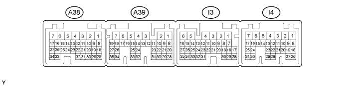
Disconnect the I3 and I4 power management control ECU connectors.
-
Measure the voltage and resistance according to the value(s) in the table below.
Tech Tips
Measure the values on the wire harness side with the connectors disconnected.
Tester Connection Wiring Color Terminal Description Condition Specified Condition I3-1 (AM22) - Body ground SB - Body ground Auxiliary battery power supply Power switch off 11 to 14 V I4-7 (AM21) - Body ground L - Body ground Auxiliary battery power supply Power switch off 11 to 14 V I3-6 (E1) - Body ground BR - Body ground Ground Always Below 1 Ω If the result is not as specified, there may be a malfunction in the wire harness.
-
Reconnect the I3 and I4 power management control ECU connectors.
-
Check for pulses according to the value(s) in the table below.
Tester Connection Wiring Color Terminal Description Condition Specified Condition I4-11 (LIN2) - I3-6 (E1) Y - BR LIN communication line Power switch on (IG) Pulse generation If the result is not as specified, the power management control ECU may be malfunctioning.
-
-
CHECK STEERING LOCK ECU (STEERING LOCK ACTUATOR ASSEMBLY)
-
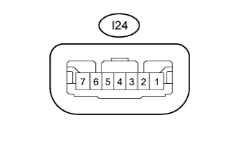
Disconnect the I24 steering lock ECU (steering lock actuator assembly) connector.
-
Measure the resistance and voltage according to the value(s) in the table below.
Terminal No. (Symbol) Wiring Color Terminal Description Condition Specified Condition I24-1 (GND) - Body ground W-B - Body ground Ground Always Below 1 Ω I24-7 (B) - Body ground B - Body ground Auxiliary battery power supply Power switch off 11 to 14 V I24-6 (IG2) - Body ground LG - Body ground IG power supply Power switch on (IG) 11 to 14 V If the result is not as specified, there may be a malfunction on the wire harness side.
-
Reconnect the I24 steering lock ECU (steering lock actuator assembly) connector.
-
Measure the voltage and check for pulses according to the value(s) in the table below.
Tester Connection Wiring Color Terminal Description Condition Specified Condition I24-5 (LIN) - I24-1 (GND) Y - W-B LIN communication line Power switch on (IG) Pulse generation If the result is not as specified, the steering lock ECU (steering lock actuator assembly) may be malfunctioning.
-