INTEGRATION RELAY REMOVAL

-
PRECAUTION
Note
After turning the power switch off, waiting time may be required before disconnecting the cable from the negative (-) auxiliary battery terminal. Therefore, make sure to read the disconnecting the cable from the negative (-) auxiliary battery terminal notices before proceeding with work Click here.
-
REMOVE LUGGAGE TRIM SERVICE HOLE COVER
-
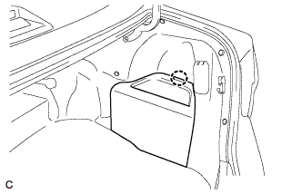
Disengage the claw to remove the luggage trim service hole cover.
-
-
DISCONNECT CABLE FROM NEGATIVE AUXILIARY BATTERY TERMINAL
Note
When disconnecting the cable, some systems need to be initialized after the cable is reconnected Click here.
-
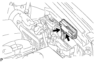
REMOVE NO. 1 RELAY BLOCK COVER
-
Disengage the 2 claws and remove the No. 1 relay block cover as shown in the illustration.
-
-
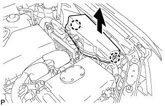
REMOVE ENGINE ROOM JUNCTION BLOCK ASSEMBLY
-
Disengage the 2 claws as shown in the illustration.
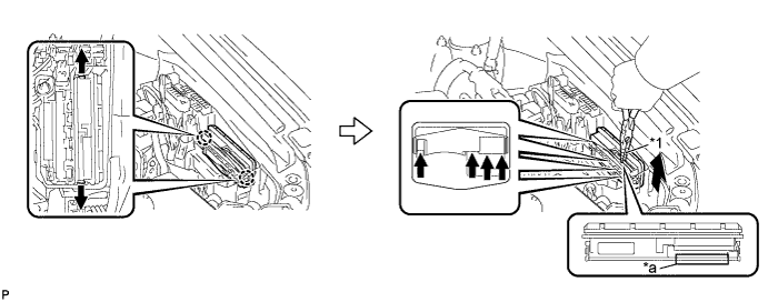
Text in Illustration *1 Protective Tape - - *a Pulled Position - - -
Using pliers, pull up the engine room junction block assembly at the position indicated in the illustration and disconnect the 4 connectors from the engine room relay block assembly.
Note
When pulling a engine room junction block assembly, take care not to damage the engine room junction block assembly.
Tech Tips
Tape the pliers tips before use.
-
Disconnect the 2 connectors and remove the engine room junction block assembly.
Note
-
Do not drop or allow any impact on parts.
-
Do not touch the connector.
-
-