NAVIGATION RECEIVER REMOVAL

-
PRECAUTION
Note
After turning the power switch off, waiting time may be required before disconnecting the cable from the negative (-) auxiliary battery terminal. Therefore, make sure to read the disconnecting the cable from the negative (-) auxiliary battery terminal notices before proceeding with work Click here.
-
REMOVE LUGGAGE TRIM SERVICE HOLE COVER
-
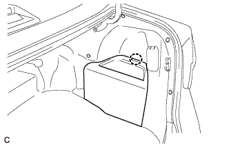
Disengage the claw to remove the luggage trim service hole cover.
-
-
DISCONNECT CABLE FROM NEGATIVE AUXILIARY BATTERY TERMINAL
Note
When disconnecting the cable, some systems need to be initialized after the cable is reconnected Click here.
-
REMOVE UPPER CONSOLE BOX SUB-ASSEMBLY
-
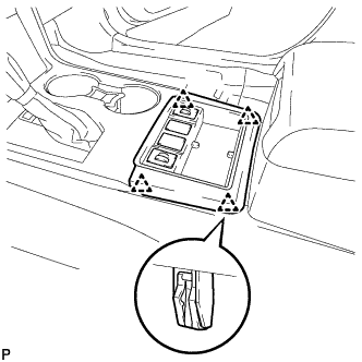
Disengage the 4 clips.
-
Disconnect each connector and remove the upper console box sub-assembly.
-
-
REMOVE SHIFT LEVER KNOB SUB-ASSEMBLY
-
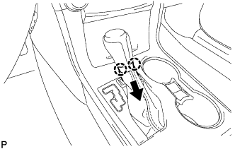
Disengage the 2 claws as shown in the illustration.
-
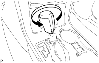
Turn the shift lever knob sub-assembly counterclockwise and remove the shift lever knob sub-assembly.
-
-
REMOVE REAR CONSOLE UPPER PANEL SUB-ASSEMBLY
-
Move the shift lever to N.
-
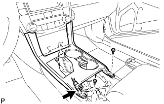
Disconnect the connector.
-
Remove the 2 screws <C> or <D>.
-
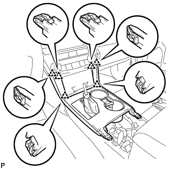
Disengage the 6 clips and remove the rear console upper panel sub-assembly.
-
-
REMOVE NO. 1 SPEAKER OPENING COVER ASSEMBLY
-
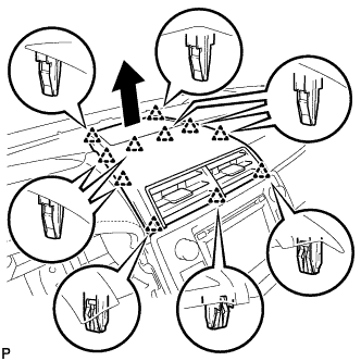
Using a moulding remover, disengage the 11 clips as shown in the illustration.
-
Disconnect the connector to remove the No. 1 speaker opening cover assembly.
-
-
REMOVE UPPER CONSOLE PANEL SUB-ASSEMBLY
-
Remove the 2 screws <C> or <D>.
-
Disengage the 2 clips and guide as shown in the illustration.
-
Disconnect each connector to remove the upper console panel sub-assembly.
-
-
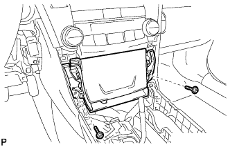
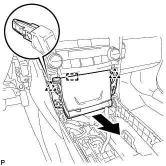
REMOVE NAVIGATION RECEIVER ASSEMBLY WITH AIR CONDITIONING CONTROL ASSEMBLY
-
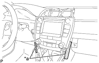
Text in Illustration *a Protective Tape Apply protective tape to the areas shown in the illustration.
-
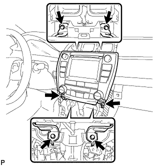
Remove the 4 bolts and 2 screws.
-
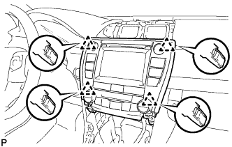
Pull the navigation receiver assembly with air conditioning control assembly toward the rear of the vehicle to disengage the 4 clips.
-
Disconnect each connector and remove the navigation receiver assembly with air conditioning control assembly.
-
-
REMOVE NAVIGATION WIRE (w/ Satellite Radio)
-
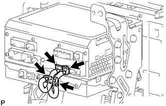
Disconnect each connector to remove the navigation wire.
-
-
REMOVE NO. 1 RADIO RECEIVER BRACKET
-
w/o Satellite Radio:
-
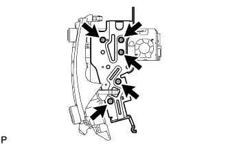
Remove the 5 screws and No. 1 radio receiver bracket.
-
-
w/ Satellite Radio:
-
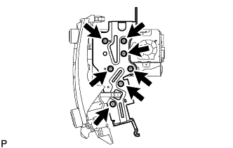
Remove the 7 screws and No. 1 radio receiver bracket.
-
-
-
REMOVE NO. 2 RADIO RECEIVER BRACKET
-
w/o Satellite Radio:
-
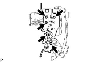
Remove the 5 screws and No. 2 radio receiver bracket.
-
-
w/ Satellite Radio:
-
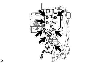
Remove the 7 screws and No. 2 radio receiver bracket.
-
-
-
REMOVE AIR CONDITIONING CONTROL ASSEMBLY
-
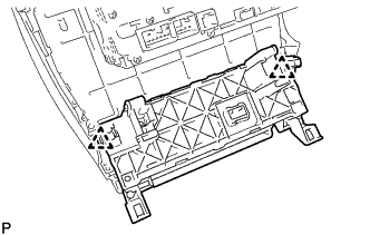
Disengage the 2 clips to remove the air conditioning control assembly.
-
-
REMOVE STEREO COMPONENT TUNER ASSEMBLY (w/ Satellite Radio)
-
REMOVE NAVIGATION RECEIVER ASSEMBLY