NAVIGATION SYSTEM, Diagnostic DTC:B1579

| DTC Code | DTC Name |
|---|---|
| B1579 | Voice Recognition Microphone Disconnected |
DESCRIPTION
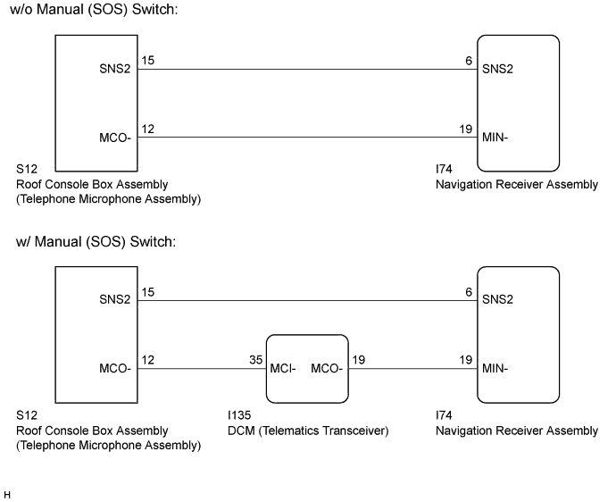
The navigation receiver assembly and roof console box assembly (telephone microphone assembly) are connected to each other using the microphone connection detection signal lines.
This DTC is stored when a microphone connection detection signal line is disconnected.
| DTC Code | DTC Detection Condition | Trouble Area |
|---|---|---|
| B1579 | Microphone signal is lost |
|
-
*: w/ Manual (SOS) Switch
WIRING DIAGRAM
INSPECTION PROCEDURE
Note
If the DCM (telematics transceiver) has been replaced, perform the DCM Activation procedure using the Techstream (w/ Manual (SOS) Switch) Click here.
PROCEDURE
-
INSPECT NAVIGATION RECEIVER ASSEMBLY
-
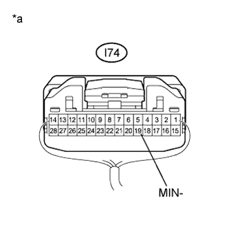
Text in Illustration *a Component with harness connected
(Navigation Receiver Assembly)
Measure the resistance according to the value(s) in the table below.
Standard Resistance Tester Connection Condition Specified Condition I74-19 (MIN-) - Body ground Always Below 1 Ω
NG 
REPLACE NAVIGATION RECEIVER ASSEMBLY Click here
OK 
-
-
CHECK MODEL
-
Choose the model to be inspected.
Result Model Proceed to w/ Manual (SOS) Switch A w/o Manual (SOS) Switch B
B 
CHECK HARNESS AND CONNECTOR (NAVIGATION RECEIVER ASSEMBLY - ROOF CONSOLE BOX ASSEMBLY (TELEPHONE MICROPHONE ASSEMBLY)) Click here
A
-
-
CHECK HARNESS AND CONNECTOR (DCM (TELEMATICS TRANSCEIVER) - ROOF CONSOLE BOX ASSEMBLY (TELEPHONE MICROPHONE ASSEMBLY))
-
Disconnect the I135 DCM (telematics transceiver) connector.
-
Disconnect the S12 roof console box assembly (telephone microphone assembly) connector.
-
Measure the resistance according to the value(s) in the table below.
Standard Resistance Tester Connection Condition Specified Condition I135-35 (MCI-) - S12-12 (MCO-) Always Below 1 Ω I135-35 (MCI-) - Body ground Always 10 kΩ or higher
NG
REPAIR OR REPLACE HARNESS OR CONNECTOR
OK
-
-
CHECK HARNESS AND CONNECTOR (NAVIGATION RECEIVER ASSEMBLY - DCM (TELEMATICS TRANSCEIVER))
-
Disconnect the I74 navigation receiver assembly connector.
-
Disconnect the I135 DCM (telematics transceiver) connector.
-
Measure the resistance according to the value(s) in the table below.
Standard Resistance Tester Connection Condition Specified Condition I74-19 (MIN-) - I135-19 (MCO-) Always Below 1 Ω I74-19 (MIN-) - Body ground Always 10 kΩ or higher
NG
REPAIR OR REPLACE HARNESS OR CONNECTOR
OK
-
-
CHECK HARNESS AND CONNECTOR (NAVIGATION RECEIVER ASSEMBLY - ROOF CONSOLE BOX ASSEMBLY (TELEPHONE MICROPHONE ASSEMBLY))
-
Disconnect the I74 navigation receiver assembly connector.
-
Disconnect the S12 roof console box assembly (telephone microphone assembly) connector.
-
Measure the resistance according to the value(s) in the table below.
Standard Resistance Tester Connection Condition Specified Condition I74-6 (SNS2) - S12-15 (SNS2) Always Below 1 Ω I74-6 (SNS2) - Body ground Always 10 kΩ or higher
NG
REPAIR OR REPLACE HARNESS OR CONNECTOR
OK
-
-
INSPECT DCM (TELEMATICS TRANSCEIVER)
-
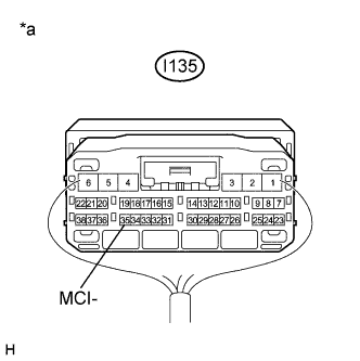
Text in Illustration *a Component with harness connected
(DCM (Telematics Transceiver))
Measure the resistance according to the value(s) in the table below.
Standard Resistance Tester Connection Condition Specified Condition I135-35 (MCI-) - Body ground Always Below 1 Ω -
Proceed to the next step based on the inspection result.
Result Result Proceed to NG A OK B
B
INSPECT ROOF CONSOLE BOX ASSEMBLY (TELEPHONE MICROPHONE ASSEMBLY) Click here
A 
REPLACE DCM (TELEMATICS TRANSCEIVER) Click here
-
-
CHECK HARNESS AND CONNECTOR (NAVIGATION RECEIVER ASSEMBLY - ROOF CONSOLE BOX ASSEMBLY (TELEPHONE MICROPHONE ASSEMBLY))
-
Disconnect the I74 navigation receiver assembly connector.
-
Disconnect the S12 roof console box assembly (telephone microphone assembly) connector.
-
Measure the resistance according to the value(s) in the table below.
Standard Resistance Tester Connection Condition Specified Condition I74-6 (SNS2) - S12-15 (SNS2) Always Below 1 Ω I74-19 (MIN-) - S12-12 (MCO-) Always Below 1 Ω I74-6 (SNS2) - Body ground Always 10 kΩ or higher I74-19 (MIN-) - Body ground Always 10 kΩ or higher
NG
REPAIR OR REPLACE HARNESS OR CONNECTOR
OK
-
-
INSPECT ROOF CONSOLE BOX ASSEMBLY (TELEPHONE MICROPHONE ASSEMBLY)
-
Remove the roof console box assembly (telephone microphone assembly) Click here.
-
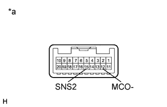
Text in Illustration *a Component without harness connected
(Roof Console Box Assembly (Telephone Microphone Assembly))
Measure the resistance according to the value(s) in the table below.
Standard Resistance Tester Connection Condition Specified Condition 15 (SNS2) - 12 (MCO-) Always Below 1 Ω
NG
REPLACE ROOF CONSOLE BOX ASSEMBLY (TELEPHONE MICROPHONE ASSEMBLY) Click here
OK
REPLACE NAVIGATION RECEIVER ASSEMBLY Click here
-