AUDIO AND VISUAL SYSTEM (w/ DVD Player), Diagnostic DTC:B158F

| DTC Code | DTC Name |
|---|---|
| B158F | AV Signal Stoppage (Low Battery Voltage) |
DESCRIPTION
This DTC is stored when a video or audio signal is interrupted due to auxiliary battery voltage input to the radio and display receiver assembly dropping temporarily.
| DTC No. | DTC Detection Condition | Trouble Area |
|---|---|---|
| B158F | A video or audio signal is interrupted when the auxiliary battery voltage drops | Radio and display receiver assembly |
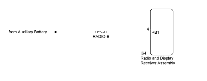
WIRING DIAGRAM
INSPECTION PROCEDURE
Note
-
Inspect the fuses for circuits related to this system before performing the following inspection procedure.
-
Depending on the parts that are replaced during vehicle inspection or maintenance, performing initialization, registration or calibration may be needed. Refer to Precaution for Audio and Visual System Click here.
PROCEDURE
-
CHECK VEHICLE SIGNAL (OPERATION CHECK)
-
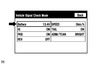
Enter the "Vehicle Signal Check Mode" screen. Refer to Check Vehicle Signal in Operation Check Click here.
-
Measure the auxiliary battery voltage.
Standard Voltage 11 to 15.5 V Tech Tips
This display is updated once per second.
NG 
CHECK HARNESS AND CONNECTOR (RADIO AND DISPLAY RECEIVER ASSEMBLY POWER SOURCE) Click here
OK 
-
-
CHECK DTC
-
Clear the DTCs Click here.
-
Recheck for DTCs and check that no DTCs are output.
OK No DTCs are output.
NG 
REPLACE RADIO AND DISPLAY RECEIVER ASSEMBLY Click here
OK 
END
-
-
CHECK HARNESS AND CONNECTOR (RADIO AND DISPLAY RECEIVER ASSEMBLY POWER SOURCE)
-
Disconnect the I64 radio and display receiver assembly connector.
-
Measure the voltage according to the value(s) in the table below.
Standard Voltage Tester Connection Condition Specified Condition I64-4 (+B1) - Body ground Power switch off 11 to 14 V
NG
REPAIR OR REPLACE HARNESS OR CONNECTOR
OK
REPLACE RADIO AND DISPLAY RECEIVER ASSEMBLY Click here
-