FRONT BRAKE FLEXIBLE HOSE INSTALLATION

Note
-
Because the left and right hoses are not interchangeable, verify the part number when installing the flexible hoses.
-
If the hoses are to be reused, connect them after checking the identification marks placed when each hose was disconnected.
Tech Tips
-
Use the same procedure for the LH side and RH side.
-
The following procedure is for the LH side.
-
INSTALL FRONT FLEXIBLE HOSE
-
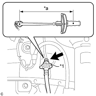
Text in Illustration *1 Clip *a Torque Wrench Fulcrum Length Install a new clip to the front flexible hose.
Note
Install the clip as far as it will go.
-
Using a union nut wrench, connect the brake line to the front flexible hose while holding the flexible hose with a wrench.
- Torque:
- Specified Tightening Torque
- 15 N*m { 155 kgf*cm, 11 ft.*lbf }
Note
-
Do not bend or damage the brake line.
-
Do not allow any foreign matter such as dirt or dust to enter the brake line from the connecting points.
Tech Tips
-
Calculate the torque wrench reading when changing the fulcrum length for the torque wrench Click here.
-
When using a union nut wrench (fulcrum length of 22 mm (0.866 in.)) + torque wrench (fulcrum length of 250 mm (9.84 in.)):
14 N*m (142 kgf*cm, 10 ft.*lbf)
-
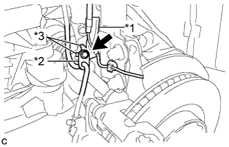
Text in Illustration *1 Front Speed Sensor Clamp *2 Front Flexible Hose *3 Claw Install the front speed sensor clamp and front flexible hose to the shock absorber bracket with the bolt.
- Torque:
- 19 N*m { 192 kgf*cm, 14 ft.*lbf }
Note
-
Do not twist the wire harness for the front speed sensor when installing it.
-
Securely set the 2 claws of the front speed sensor clamp to the shock absorber bracket.
-
A bolt tightens the brake flexible hose and front speed sensor together. Make sure that the front flexible hose is positioned over the front speed sensor.
-
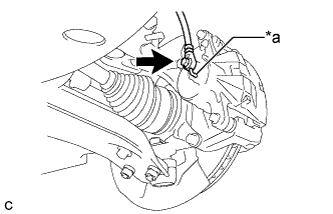
Text in Illustration *a Lock Hole Connect the front flexible hose to the front disc brake cylinder assembly with a new union bolt and a new gasket.
- Torque:
- 29 N*m { 300 kgf*cm, 22 ft.*lbf }
Note
Install the flexible hose lock securely into the lock hole in the front disc brake cylinder.
-
-
CONNECT CABLE TO AUXILIARY BATTERY NEGATIVE TERMINAL
-
BLEED BRAKE LINE
-
Bleed brake line.
-
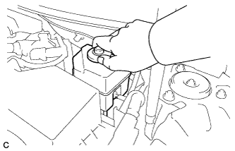
Remove the brake master cylinder reservoir filler cap assembly.
-
Add brake fluid into the reservoir between the MAX and MIN level on the brake fluid reservoir.
Brake fluid SAE J1703 or FMVSS No. 116 DOT3 -
Connect the Techstream to the DLC3 and turn the power switch on (IG).
-
Turn the Techstream on and enter the following menus: Chassis / ABS/VSC/TRAC / Air Bleeding.
-
Select "Usual air bleeding" on the Techstream display, and bleed air from the brake fluid following the instructions on the Techstream.
-
After air bleeding, tighten each bleeder plug.
- Torque:
- 8.3 N*m { 85 kgf*cm, 73 in.*lbf }
-
Clear the DTCs Click here.
-
Turn the Techstream off and turn the power switch off.
-
-
Inspect for brake fluid leaks.
-
Install the brake master cylinder reservoir filler cap.
-
-
INSTALL FRONT WHEEL
- Torque:
- 103 N*m { 1049 kgf*cm, 76 ft.*lbf }