BRAKE BOOSTER PUMP REMOVAL

-
PRECAUTION
Note
After turning the power switch off, waiting time may be required before disconnecting the cable from the negative (-) auxiliary battery terminal. Therefore, make sure to read the disconnecting the cable from the negative (-) auxiliary battery terminal notices before proceeding with work Click here.
-
RECOVER REFRIGERANT FROM AIR CONDITIONING SYSTEM
-
Turn the power switch on (READY).
-
Turn the A/C switch on.
-
Operate the cooler compressor under the conditions shown below:
Item Condition Engine Speed Idling Operating Time 3 minutes or more A/C Switch Status ON Blower Switch Status HI Set Temperature MAX COOL This cause most of the compressor oil from the various components of the A/C system to collect in the A/C compressor.
Tech Tips
It is not necessary to operate the cooler compressor if the A/C does not operate because of compressor lock etc.
-
Turn the power switch off.
-
Recover the refrigerant from the air conditioning system using a refrigerant recovery unit.
Tech Tips
Use the refrigerant recover unit in accordance with the manufacturer's instruction manual.
-
-
DISABLE BRAKE CONTROL
-
Wait at least 2 minutes after turning the power switch off.
Note
When the brake pedal is depressed or the door courtesy switch is turned on even if the power switch is off, the brake control system activates. Therefore do not depress the brake pedal or open/close the doors until the reservoir level switch connector is disconnected.
-
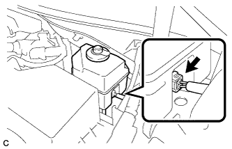
Disconnect the reservoir level switch connector with the parking brake applied.
-
Disconnect the cable from the negative (-) auxiliary battery terminal Click here.
-
Depress the brake pedal 40 times or more to return all the fluid in the accumulator back to the reservoir.
-
Check that the brake pedal can not be further depressed.
-
Release the parking brake.
-
-
REMOVE WINDSHIELD WIPER MOTOR AND LINK ASSEMBLY
-
REMOVE FRONT OUTER COWL TOP PANEL SUB-ASSEMBLY
-
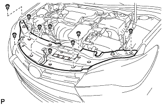
Disengage the 2 clamps and separate the wire harness from the front outer cowl top panel sub-assembly.
-
Remove the 10 bolts and front outer cowl top panel sub-assembly.
-
-
REMOVE COOL AIR INTAKE DUCT SEAL
-
Remove the 9 clips and cool air intake duct seal.
-
-
REMOVE INLET AIR CLEANER ASSEMBLY
-
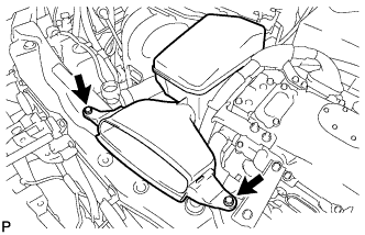
Remove the 2 bolts and inlet air cleaner assembly.
-
-
REMOVE AIR CLEANER CAP SUB-ASSEMBLY
-
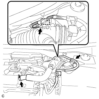
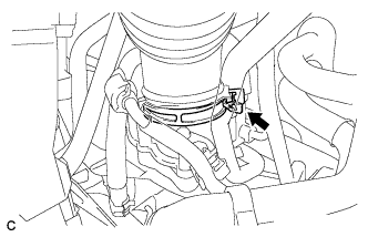
Disconnect the mass air flow meter connector and wire harness clamp from the air cleaner cap sub-assembly.
-
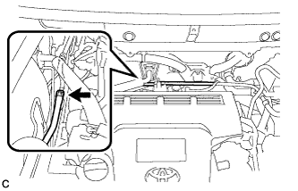
Disconnect the ventilation hose from the cylinder head cover.
-
Disconnect the connector and wire harness clamp.
-
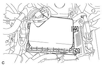
Release the 2 clamps and remove the air cleaner cap sub-assembly.
-
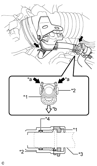
Text in Illustration *1 Retainer *2 Fuel Tube Connector *3 Pipe *4 O-ring *a Pinch *b Pull Disconnect the 2 fuel vapor feed hoses.
Note
-
Remove any dirt or foreign matter on the fuel tube connector before performing this work.
-
Do not allow any scratches or foreign matter to get on the parts when disconnecting them as the fuel tube connector has an O-ring that seals the pipe.
-
Perform this work by hand. Do not use any tools.
-
Protect the disconnected parts by covering them with plastic bags after disconnecting each fuel vapor feed hose.
-
-
Loosen the hose clamp and disconnect the air cleaner hose from the throttle with motor body assembly.
-
-
REMOVE AIR CLEANER FILTER ELEMENT SUB-ASSEMBLY
-
REMOVE AIR CLEANER CASE SUB-ASSEMBLY
-
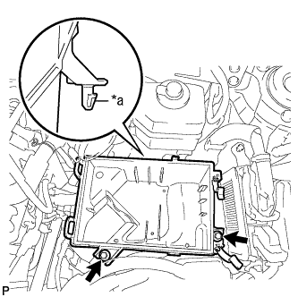
Text in Illustration *a Projection Remove the 2 bolts and air cleaner case sub-assembly.
-
-
SEPARATE AIR CONDITIONER TUBE AND ACCESSORY ASSEMBLY
-
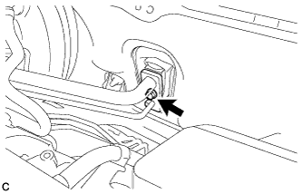
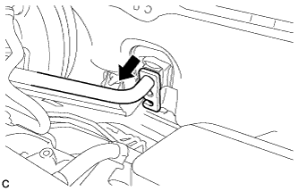
Remove the bolt from the hook connector.
-
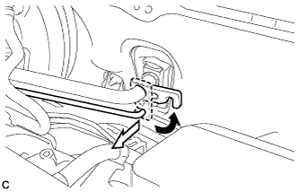
Turn the hook connector and separate the air conditioning tube and accessory assembly from the air conditioning unit.
Note
-
Do not deform the piping.
-
Do not damage the plastic clamp.
-
-
Remove the O-ring from the air conditioning tube and accessory assembly.
Note
Seal the openings of the disconnected parts using vinyl tape to prevent entry of moisture and foreign matter.
-
-
SEPARATE SUCTION HOSE SUB-ASSEMBLY
-
Separate the suction hose sub-assembly from the air conditioning unit.
Note
-
Do not deform the piping.
-
Do not damage the plastic clamp.
-
-
Remove the O-ring from the suction hose sub-assembly.
Note
Seal the openings of the disconnected parts using vinyl tape to prevent entry of moisture and foreign matter.
-
-
DRAIN BRAKE FLUID
Note
If brake fluid leaks onto any painted surface, immediately clean it off.
-
SEPARATE BRAKE MASTER CYLINDER RESERVOIR ASSEMBLY
-
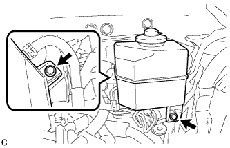
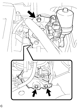
Remove the 2 bolts and brake master cylinder reservoir assembly.
-
-
SEPARATE NO. 1 BRAKE ACTUATOR TUBE
-
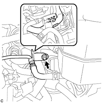
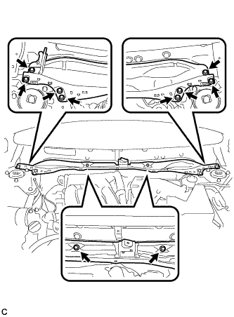
Remove the nut and disengage the clamp.
-
Remove the nut and separate the No. 1 brake actuator tube from the vehicle body.
-
-
DISCONNECT NO. 1 BRAKE ACTUATOR HOSE
-
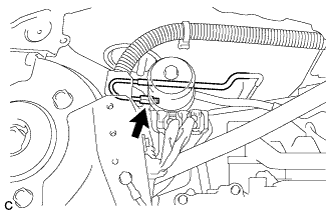
Move the clip and disconnect the No. 1 brake actuator hose from the No. 1 brake actuator tube.
-
-
DISCONNECT FRONT NO. 1 BRAKE TUBE
-
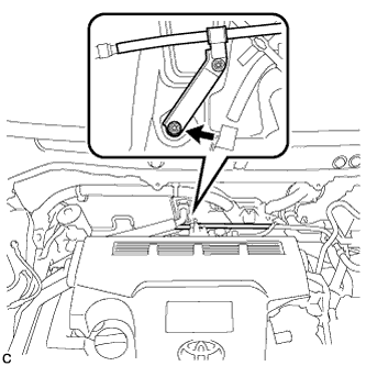
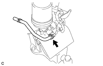
Using a union nut wrench, disconnect the front No. 1 brake tube from the brake booster pump assembly.
-
-
REMOVE BRAKE BOOSTER PUMP ASSEMBLY WITH BRACKET
-
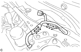
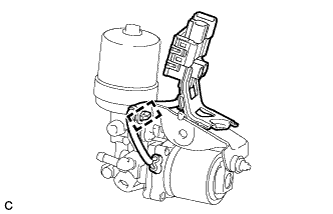
Disconnect the 2 connectors from the brake booster pump assembly.
-
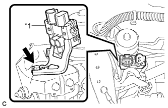
Text in Illustration *1 Connector Box Remove the bolt and separate the connector box of the brake booster pump assembly from the brake actuator bracket assembly.
-
Remove the 3 bolts and brake booster pump assembly with bracket from the vehicle body.
Note
Do not kink or damage the brake line, suction hose sub-assembly or air conditioning tube and accessory assembly.
-
-
REMOVE NO. 1 BRAKE ACTUATOR HOSE
-
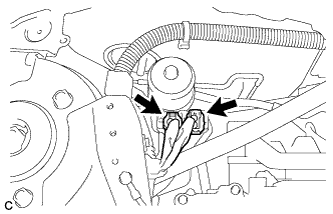
Move the clip and remove the No. 1 brake actuator hose from the brake booster pump assembly.
-
-
REMOVE BRAKE BOOSTER PUMP ASSEMBLY
-
Disengage the wire harness clamp from the brake actuator bracket assembly.
-
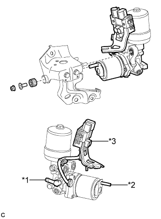
Text in Illustration *1 Union *2 Stud *3 Connector Box and Wire Harness Remove the nut, brake actuator case collar, brake booster pump bushing and brake booster pump assembly from the brake actuator bracket assembly.
Note
-
Do not carry the brake booster pump assembly by the parts shown in bold (*1, *2 and *3) in the illustration.
-
Do not drop the brake booster pump assembly when carrying it.
-
Be careful not to allow any brake fluid to enter the connector.
-
-