BRAKE BOOSTER INSTALLATION

-
INSTALL BRAKE BOOSTER GASKET
-
Install a new brake booster gasket to the brake booster with master cylinder assembly.
-
-
INSTALL BRAKE BOOSTER WITH MASTER CYLINDER ASSEMBLY
-
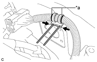
Text in Illustration *a Matchmark 
Cut 
Disposal Portion Align the matchmarks on the wire harness and a new wire harness clamp, and install it to the wire harness.
Note
Make sure to install the wire harness clamp in the correct direction.
-
Tighten the bands of the clamp and cut off the excess.
-
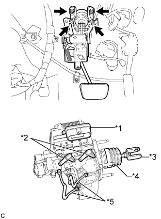
Text in Illustration *1 Connector Portion *2 Union *3 Push Rod Clevis *4 Boot *5 Front No. 2 Brake Tube Install the brake booster with master cylinder assembly with the 4 nuts.
- Torque:
- 13 N*m { 131 kgf*cm, 9 ft.*lbf }
Note
-
Do not kink or damage the brake lines.
-
Do not carry the brake booster with master cylinder assembly by the parts shown in bold in the illustration.
-
Be careful not to allow any brake fluid to enter the connector.
-
If installing a new brake booster with master cylinder assembly, do not remove the hole plugs before connecting the brake lines because the brake booster with master cylinder is filled with brake fluid.
-
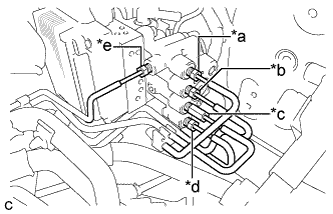
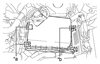
Text in Illustration *a to Front Wheel Cylinder LH *b to Rear Wheel Cylinder RH *c to Brake Booster Pump Assembly *d to Rear Wheel Cylinder LH *e to Front Wheel Cylinder RH Temporarily tighten each brake line to the correct position on the brake booster with master cylinder assembly as shown in the illustration.
-
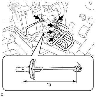
Text in Illustration *a Torque Wrench Fulcrum Length Using a union nut wrench, fully tighten each brake line.
- Torque:
- Specified tightening torque
- 15 N*m { 155 kgf*cm, 11 ft.*lbf }
Note
Do not kink or damage the brake lines.
Tech Tips
-
Calculate the torque wrench reading when changing the fulcrum length of the torque wrench Click here.
-
When using a union nut wrench (fulcrum length of 22 mm (0.866 in.)) + torque wrench (fulcrum length of 250 mm (9.84 in.)):
14 N*m (142 kgf*cm, 10 ft.*lbf)
-
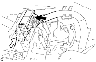
Connect the connector to the brake booster with master cylinder assembly.
Text in Illustration Connect the connector 
Lock the lock lever Note
-
Make sure that the connector can be connected smoothly. Do not allow water, oil or dirt to enter.
-
Make sure that the connector lock is locked securely.
-
-
Push in the wire harness clamp to install it to the brake booster with master cylinder assembly.
-
-
INSTALL RESERVOIR BRACKET
-
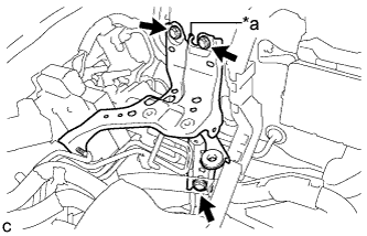
Text in Illustration *a Claw Engage the claw to set the reservoir bracket to the vehicle body.
-
Install the 3 bolts to secure the reservoir bracket to the vehicle body.
- Torque:
- 19 N*m { 194 kgf*cm, 14 ft.*lbf }
-
Engage the 2 clamps to install the wire harness to the reservoir bracket.
-
-
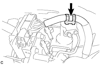
CONNECT NO. 1 RESERVOIR HOSE
-
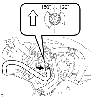
Connect the No. 1 reservoir hose to the brake booster with master cylinder assembly with the clip.
Text in Illustration Up Note
-
When connecting the No. 1 reservoir hose, face the identification mark up.
-
Match the identification mark of the No. 1 reservoir hose and the rib of the brake booster with master cylinder assembly.
-
Make sure to install the hose to the proper location.
-
Install the clip within the range shown in the illustration.
-
-
-
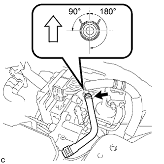
CONNECT NO. 2 RESERVOIR HOSE
-
Connect the No. 2 reservoir hose to the brake booster with master cylinder assembly with the clip.
Text in Illustration Up Note
-
When connecting the No. 2 reservoir hose, face the identification mark up.
-
Match the identification mark of the No. 2 reservoir hose and the identification mark of the brake booster with master cylinder assembly.
-
Make sure to install the hose to the proper location.
-
Install the clip within the range shown in the illustration.
-
-
-
BLEED NO. 1 BRAKE ACTUATOR TUBE
-
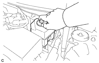
Add brake fluid into the brake master cylinder reservoir assembly.
-
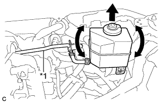
Text in Illustration *1 No. 1 Brake Actuator Tube Lift up the brake master cylinder reservoir assembly as far as possible and rock it back and forth to bleed air from the reservoir tube assembly.
Note
-
Do not damage the hoses or tubes.
-
Do not spill the brake fluid.
-
Continue this procedure until only a minor amount of air remains in the No. 1 brake actuator tube.
-
-
-
INSTALL NO. 1 BRAKE ACTUATOR TUBE
-
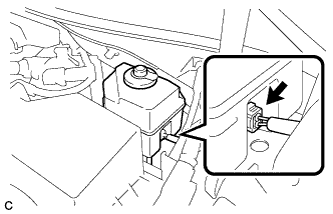
Install the No. 1 brake actuator tube to the vehicle body with the nut.
- Torque:
- 8.5 N*m { 87 kgf*cm, 75 in.*lbf }
-
Install the nut and engage the clamp.
- Torque:
- 8.5 N*m { 87 kgf*cm, 75 in.*lbf }
-
-
INSTALL BRAKE MASTER CYLINDER RESERVOIR ASSEMBLY
-
Install the brake master cylinder reservoir assembly to the reservoir bracket with the 2 bolts.
- Torque:
- 8.5 N*m { 87 kgf*cm, 75 in.*lbf }
-
-
INSTALL PUSH ROD PIN
-
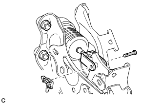
Apply lithium soap base glycol grease to the push rod pin.
Text in Illustration Lithium Soap Base Glycol Grease -
Connect the brake master cylinder push rod clevis to the brake pedal support assembly with the push rod pin, and install a new clip as shown in the illustration.
Note
-
Be sure to insert the pin with its clip end facing the outside of the vehicle.
-
Make sure that the brake master cylinder push rod clevis moves sideway.
-
-
-
FILL RESERVOIR WITH BRAKE FLUID
-
CONNECT CABLE TO AUXILIARY BATTERY NEGATIVE TERMINAL
-
BLEED BRAKE SYSTEM
-
Remove the front outer cowl top panel sub-assembly Click here.
-
Bleed the brake system.
-
Wait at least 2 minutes with the power switch off, and disconnect the reservoir level switch connector.
Note
Do not depress the brake pedal or open/close the doors until the reservoir level switch connector is disconnected.
Tech Tips
This procedure is not required if the reservoir level switch connector has been disconnected.
-
Remove the brake master cylinder reservoir filler cap assembly.
-
Add brake fluid into the reservoir between the MAX and MIN level on the brake fluid reservoir.
Brake fluid SAE J1703 or FMVSS No. 116 DOT3 -
Connect the Techstream to the DLC3 and turn the power switch on (IG).
-
Turn the Techstream on and enter the following menus: Chassis / ABS/VSC/TRAC / Air Bleeding.
-
Select "ABS actuator has been replaced" on the Techstream display, and bleed air from the brake fluid following the instructions on the Techstream.
Note
Before following the instructions on the Techstream to perform linear valve offset calibration, release the parking brake. When calibration is complete, immediately apply the parking brake.
-
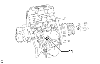
Text in Illustration *1 Stroke Simulator Bleeder Plug After air bleeding, tighten each bleeder plug.
- Torque:
- disc brake cylinder bleeder plug
- 8.3 N*m { 85 kgf*cm, 73 in.*lbf }
- stroke simulator bleeder plug
- 8.5 N*m { 87 kgf*cm, 75 in.*lbf }
Tech Tips
The stroke simulator bleeder plug is positioned as shown in the illustration.
-
Clear the DTCs Click here.
-
Turn the Techstream off and turn the power switch off.
-
-
Install the brake master cylinder reservoir filler cap.
-
Inspect for brake fluid leaks.
-
Install the outer cowl top panel sub-assembly Click here.
-
-
INSTALL AIR CLEANER CASE SUB-ASSEMBLY
-
Text in Illustration *a Projection Insert the projection of the air cleaner case sub-assembly into the hole of the No. 2 air cleaner bracket as shown in the illustration.
-
Tighten the 2 bolts.
- Torque:
- 5.0 N*m { 51 kgf*cm, 44 in.*lbf }
-
-
INSTALL AIR CLEANER FILTER ELEMENT SUB-ASSEMBLY
-
INSTALL AIR CLEANER CAP SUB-ASSEMBLY
-
Install the air cleaner hose with the hose clamp.
-
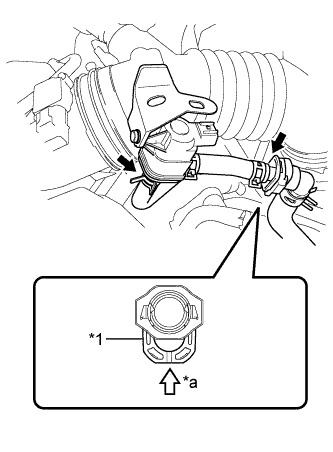
Text in Illustration *1 Retainer *a Push Connect the 2 fuel vapor feed hoses.
Note
-
Check that there are no scratches or foreign matter around the connected part of the fuel tube connector and pipe before performing this work.
-
Connect the quick connector and push the retainer in until the retainer makes a "click" sound to lock the claws of the retainer.
-
After connecting the fuel vapor feed hose to the fuel tube connector, check that the fuel vapor feed hose is securely connected by pulling on the fuel tube connector and the fuel vapor feed hose.
-
-
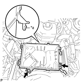
Text in Illustration *a Hinge *b Clamp Connect the 2 hinges of the air cleaner cap subassembly.
-
Install the air cleaner cap sub-assembly with the 2 clamps.
-
Connect the wire harness clamp and connector.
-
Connect the ventilation hose to the cylinder head cover.
-
Connect the mass air flow meter connector and wire harness clamp to the air cleaner cap sub-assembly.
-
-
INSTALL INLET AIR CLEANER ASSEMBLY
-
Install the inlet air cleaner assembly with the 2 bolts.
- Torque:
- 8.0 N*m { 82 kgf*cm, 71 in.*lbf }
-
-
INSTALL COOL AIR INTAKE DUCT SEAL
-
Install the cool air intake duct seal with the 9 clips.
-
-
INSTALL FRONT OUTER COWL TOP PANEL SUB-ASSEMBLY
-
Install the front outer cowl top panel sub-assembly with the 10 bolts.
- Torque:
- 10 N*m { 102 kgf*cm, 7 ft.*lbf }
-
Engage the 2 clamps to install the wire harness to the front outer cowl top panel sub-assembly.
-
-
INSTALL WINDSHIELD WIPER MOTOR AND LINK ASSEMBLY
-
INSPECT AND ADJUST BRAKE PEDAL
-
OBTAIN ZERO POINT OF YAW RATE AND ACCELERATION SENSOR
Tech Tips
After the brake booster with master cylinder assembly is replaced, obtain the zero point of the yaw rate and acceleration sensor Click here.