FRONT LOWER SUSPENSION ARM INSTALLATION

-
INSTALL FRONT LOWER NO. 1 SUSPENSION ARM SUB-ASSEMBLY LH (for LH Side)
-
Install the front lower arm bushing stopper to the front lower No. 1 suspension arm sub-assembly LH.
-
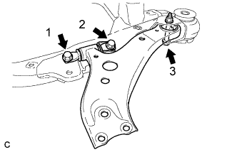
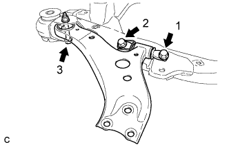
Install the front lower No. 1 suspension arm sub-assembly LH to the front frame assembly with the 3 bolts and nut in the order shown in the illustration.
- Torque:
- Bolt 1, 2
- 200 N*m { 2039 kgf*cm, 148 ft.*lbf }
- Bolt 3
- 135 N*m { 1377 kgf*cm, 100 ft.*lbf }
Note
While keeping the nut from rotating, tighten the bolt.
-
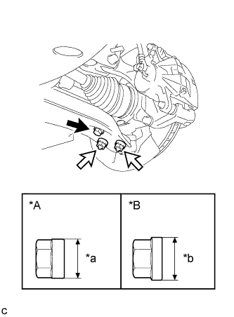
Text in Illustration *A Type A Nut *B Type B Nut *a 20 mm (0.787 in.) *b 22 mm (0.866 in.) 
Bolt 
Nut Install the front lower No. 1 suspension arm sub-assembly LH to the front lower ball joint assembly with the bolt and 2 nuts.
- Torque:
- Type A Nut and Bolt
- 75 N*m { 765 kgf*cm, 55 ft.*lbf }
- Type B Nut and Bolt
- 92 N*m { 938 kgf*cm, 68 ft.*lbf }
Note
-
The tightening torque for the bolt differs depending on the type of nut.
-
Make sure to tighten the bolt to the same torque as the nuts.
-
-
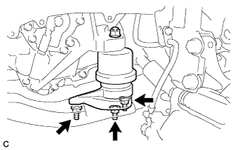
INSTALL ENGINE MOUNTING INSULATOR LH (for LH Side)
-
Text in Illustration *a Pin Set the engine mounting insulator LH on the front frame assembly.
-
Slowly lower the engine assembly with transaxle using a jack and a wooden block.
Note
-
Match the position of the pin (stopper).
-
Do not position the wooden block on the oil pan.
-
Do not damage the components surrounding the engine assembly with transaxle.
-
Ensure that the jack and wooden block are stable.
-
-
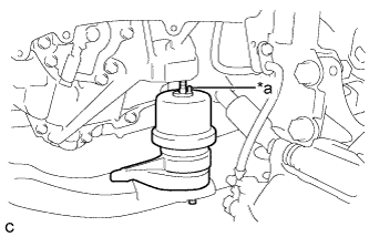
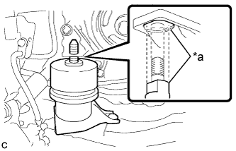
Text in Illustration *a Torque Wrench Fulcrum Length Using SST, install the nut to the engine mounting insulator LH.
- SST
- 09961-00950
- Torque:
- Specified tightening torque
- 95 N*m { 969 kgf*cm, 70 ft.*lbf }
Note
This torque value is effective when SST is parallel to the torque wrench.
Tech Tips
-
Calculate the torque wrench reading when changing the fulcrum length of the torque wrench.
-
When using SST (fulcrum length of 150 mm (5.91 in.)) + torque wrench (fulcrum length of 380 mm (1.25 ft.)):
68 N*m (695 kgf*cm, 50 ft.*lbf)
-
Install the engine mounting insulator LH with the 3 nuts.
- Torque:
- 99 N*m { 1010 kgf*cm, 73 ft.*lbf }
-
Install the 2 hole plugs.
-
-
INSTALL FRONT LOWER NO. 1 SUSPENSION ARM SUB-ASSEMBLY RH (for RH Side)
-
Install the front lower arm bushing stopper to the front lower No. 1 suspension arm sub-assembly RH.
-
Install the front lower No. 1 suspension arm sub-assembly RH to the front frame assembly with the 3 bolts and nut in the order shown in the illustration.
- Torque:
- Bolt 1, 2
- 200 N*m { 2039 kgf*cm, 148 ft.*lbf }
- Bolt 3
- 135 N*m { 1377 kgf*cm, 100 ft.*lbf }
Note
While keeping the nut from rotating, tighten the bolt.
-
Text in Illustration *A Type A Nut *B Type B Nut *a 20 mm (0.787 in.) *b 22 mm (0.866 in.) Bolt Nut Install the front lower No. 1 suspension arm sub-assembly LH to the front lower ball joint assembly with the bolt and 2 nuts.
- Torque:
- Type A Nut and Bolt
- 75 N*m { 765 kgf*cm, 55 ft.*lbf }
- Type B Nut and Bolt
- 92 N*m { 938 kgf*cm, 68 ft.*lbf }
Note
-
The tightening torque for the bolt differs depending on the type of nut.
-
Make sure to tighten the bolt to the same torque as the nuts.
-
-
INSTALL ENGINE MOUNTING INSULATOR RH (for RH Side)
-
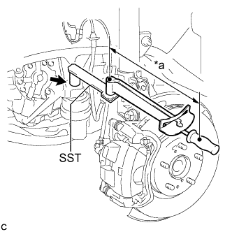
Text in Illustration *a Cutout Set the engine mounting insulator RH on the front frame assembly.
-
Slowly lower the engine assembly with transaxle using a jack and a wooden block.
Note
-
Match the position of the cutout (stopper).
-
Do not position the wooden block on the oil pan.
-
Do not damage the components surrounding the engine assembly with transaxle.
-
Ensure that the jack and wooden block are stable.
-
-
Text in Illustration *a Torque Wrench Fulcrum Length Using SST, install the nut to the engine mounting insulator RH.
- SST
- 09961-00950
- Torque:
- Specified tightening torque
- 95 N*m { 969 kgf*cm, 70 ft.*lbf }
Note
This torque value is effective when SST is parallel to the torque wrench.
Tech Tips
-
Calculate the torque wrench reading when changing the fulcrum length of the torque wrench.
-
When using SST (fulcrum length of 150 mm (5.91 in.)) + torque wrench (fulcrum length of 380 mm (1.25 ft.)):
68 N*m (695 kgf*cm, 50 ft.*lbf)
-
Install the engine mounting insulator RH with the 3 nuts.
- Torque:
- 99 N*m { 1010 kgf*cm, 73 ft.*lbf }
-
Install the 2 hole plugs.
-
-
INSTALL FRONT ENGINE MOUNTING INSULATOR
-
Install the front engine mounting insulator to the front frame assembly with the 3 nuts.
- Torque:
- 58 N*m { 591 kgf*cm, 43 ft.*lbf }
-
-
CONNECT OXYGEN SENSOR
-
Connect the oxygen sensor connector.
-
-
CONNECT NO. 4 ENGINE WIRE
-
Connect the No. 4 engine wire to the front frame assembly with the bolt.
- Torque:
- 8.0 N*m { 82 kgf*cm, 71 in.*lbf }
-
-
INSTALL FRONT FENDER APRON SEAL LH (for LH Side)
-
INSTALL FRONT FENDER APRON SEAL RH (for RH Side)
-
INSTALL ENGINE UNDER COVER LH
-
INSTALL ENGINE UNDER COVER RH
-
INSTALL FRONT WHEEL OPENING EXTENSION PAD LH
-
INSTALL FRONT WHEEL OPENING EXTENSION PAD RH
-
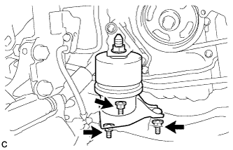
INSTALL ENGINE MOVING CONTROL ROD BRACKET
-
Temporarily install the engine moving control rod bracket with the 4 bolts.
-
Fully tighten the engine moving control rod bracket with the 4 bolts.
- Torque:
- 38 N*m { 387 kgf*cm, 28 ft.*lbf }
-
-
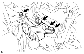
INSTALL NO. 2 ENGINE MOUNTING STAY RH
-
Install the No. 2 engine mounting stay RH with the 2 bolts.
- Torque:
- 38 N*m { 387 kgf*cm, 28 ft.*lbf }
-
-
INSTALL EARTH WIRE
-
Install the earth wire to the engine moving control rod bracket with the bolt.
- Torque:
- 8.0 N*m { 82 kgf*cm, 71 in.*lbf }
-
-
INSTALL FRONT OUTER COWL TOP PANEL SUB-ASSEMBLY
-
Install the front outer cowl top panel sub-assembly with the 10 bolts.
- Torque:
- 10 N*m { 102 kgf*cm, 7 ft.*lbf }
-
Engage the 2 clamps to install the wire harness to the front outer cowl top panel sub-assembly.
-
-
INSTALL WINDSHIELD WIPER MOTOR AND LINK ASSEMBLY
-
INSTALL FRONT WHEELS
- Torque:
- 103 N*m { 1049 kgf*cm, 76 ft.*lbf }
-
INSTALL INVERTER WITH CONVERTER ASSEMBLY
-
INSPECT AND ADJUST FRONT WHEEL ALIGNMENT