HYBRID VEHICLE TRANSAXLE (When Using the Engine Support Bridge) INSTALLATION

-
INSTALL WITH HEAD STRAIGHT SCREW PLUG
Tech Tips
Perform this procedure only when replacement of the with head straight screw plug is necessary.
-
Coat a new O-ring with ATF and install it to the with head straight screw plug.
-
Using a 10 mm hexagon socket wrench, install the with head straight screw plug to the hybrid vehicle transaxle assembly.
- Torque:
- 25 N*m { 250 kgf*cm, 18 ft.*lbf }
-
-
INSTALL NO. 1 INVERTER COOLING HOSE ASSEMBLY
-
Install the No. 1 inverter cooling hose assembly to the hybrid vehicle transaxle assembly.
-
-
INSTALL WIRE HARNESS CLAMP BRACKET
-
Install the 2 wire harness clamp brackets to the hybrid vehicle transaxle assembly with the 3 bolts.
- Torque:
- 8.0 N*m { 82 kgf*cm, 71 in.*lbf }
-
-
INSTALL HYBRID TRANSAXLE MASS DAMPER
-
Install a new gasket and the hybrid transaxle mass damper to the hybrid vehicle transaxle assembly.
- Torque:
- 39 N*m { 400 kgf*cm, 29 ft.*lbf }
-
-
INSTALL NO. 3 AUTOMATIC TRANSMISSION CASE COVER
-
Install the No. 3 automatic transmission case cover to the hybrid vehicle transaxle assembly with the 2 bolts and a new clip.
- Torque:
- 7.0 N*m { 71 kgf*cm, 62 in.*lbf }
-
-
INSTALL AUTOMATIC TRANSMISSION CASE COVER
-
Engage the 2 guides to install the automatic transmission case cover to the No. 3 automatic transmission case cover.
-
-
INSTALL NO. 3 TRANSMISSION CONTROL CABLE BRACKET
-
Install the No. 3 transmission control cable bracket to the hybrid vehicle transaxle assembly with the bolt.
- Torque:
- 12 N*m { 122 kgf*cm, 9 ft.*lbf }
-
-
INSTALL NO. 2 TRANSMISSION CONTROL CABLE BRACKET
-
Install the No. 2 transmission control cable bracket to the hybrid vehicle transaxle assembly with the bolt.
- Torque:
- 12 N*m { 122 kgf*cm, 9 ft.*lbf }
-
-
INSTALL NO. 1 TRANSMISSION CONTROL CABLE BRACKET
-
Install the No. 1 transmission control cable bracket to the hybrid vehicle transaxle assembly with the 2 bolts.
- Torque:
- 12 N*m { 122 kgf*cm, 9 ft.*lbf }
-
-
INSTALL FRONT ENGINE MOUNTING BRACKET
-
Install the front engine mounting bracket to the hybrid vehicle transaxle assembly with the 3 bolts.
- Torque:
- 64 N*m { 653 kgf*cm, 47 ft.*lbf }
-
-
SUPPORT ENGINE ASSEMBLY
-
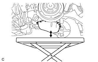
Set an engine lifter.
Note
Make sure that there is a clearance between the oil pan sub-assembly and engine lifter.
-
-
INSTALL HYBRID VEHICLE TRANSAXLE ASSEMBLY
-
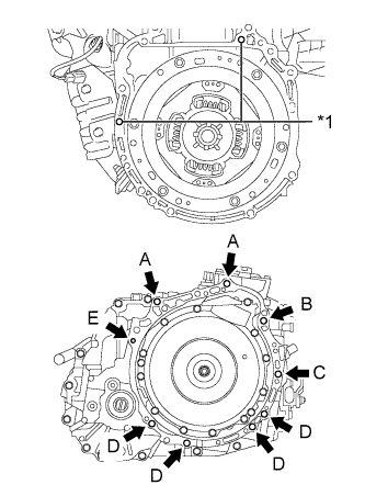
Text in Illustration *1 Knock Pin While keeping the engine assembly and hybrid vehicle transaxle assembly horizontal, align the 2 knock pins with each hole on the hybrid vehicle transaxle assembly and tighten the 9 bolts shown in the illustration.
-
Install the hybrid vehicle transaxle assembly to the engine assembly with the 9 bolts.
Bolt Bolt Length Torque (A), (B) 55 mm (2.17 in.) 64 N*m (653 kgf*cm, 47 ft.*lbf) (C) 65 mm (2.56 in.) 46 N*m (469 kgf*cm, 34 ft.*lbf) (D) 32 mm (1.26 in.) 44 N*m (449 kgf*cm, 32 ft.*lbf) 33 mm (1.30 in.) 43 N*m (438 kgf*cm, 32 ft.*lbf) (E) 38 mm (1.50 in.) 28 N*m (286 kgf*cm, 21 ft.*lbf) Note
-
Do not apply grease either to the inner splines or to the input shaft.
-
Make sure that the wire harness or other similar items are not pinched between the contact surfaces.
-
Do not use excessive force when installing the hybrid vehicle transaxle assembly.
-
Make sure to align the hybrid vehicle transaxle assembly so that the input shaft of the hybrid vehicle transaxle assembly will be inserted straight into the inner splines of the transmission input damper assembly.
-
When inserting the input shaft of the hybrid vehicle transaxle assembly into the inner splines of the transmission input damper assembly, do not shake the hybrid vehicle transaxle assembly excessively.
-
When mounting the hybrid vehicle transaxle assembly to the engine assembly, make sure to securely fit the knock pins into the knock pin holes.
-
Confirm that the 2 knock pins are installed to the hybrid vehicle transaxle assembly contact surface of the engine assembly before installing the hybrid vehicle transaxle assembly.
-
Make sure that the engine assembly and hybrid vehicle transaxle assembly are flat against each other before tightening the bolts.
-
To prevent the motor water jacket cover assembly from being deformed, do not place any attachments under the motor water jacket cover assembly of the hybrid vehicle transaxle assembly.
-
Secure the hybrid vehicle transaxle assembly to the transmission jack using a belt, etc. to prevent it from falling.
Tech Tips
Temporarily install the bolt (B) first.
-
-
-
INSTALL BELT
-
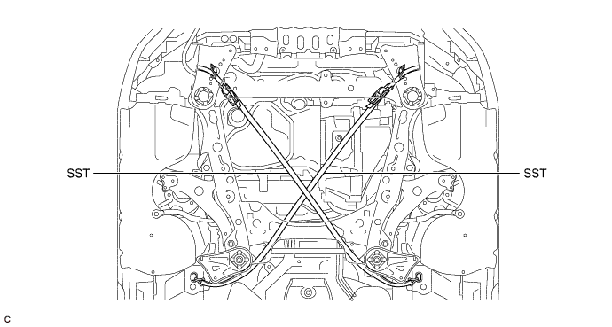
Install SST to the vehicle body as shown in the illustration.
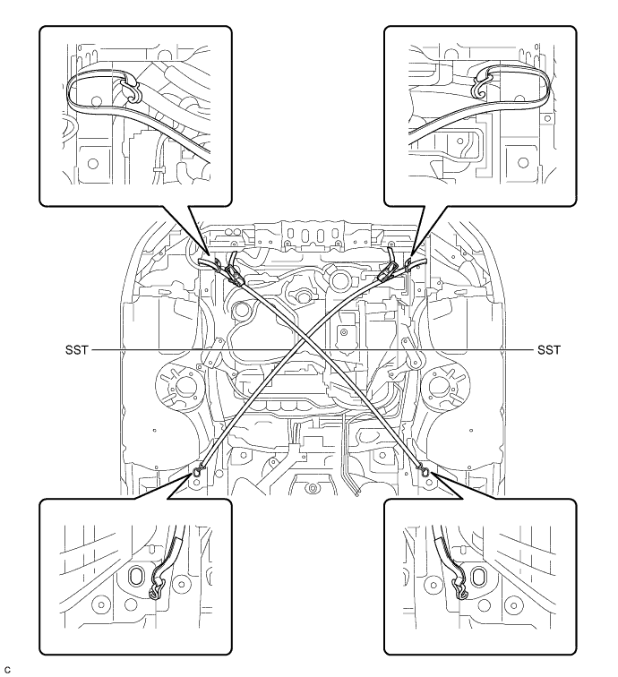
- SST
- 09727-00110
-
Using the SST ratchet buckle, tighten the SST belt until there is no slack.
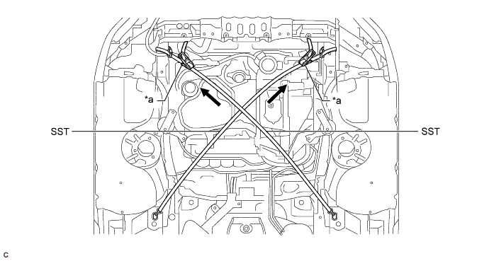
Text in Illustration *a Ratchet Buckle - -
-
-
INSTALL ENGINE MOUNTING INSULATOR LH
-
Install the engine mounting insulator LH to the hybrid vehicle transaxle assembly with the nut.
- Torque:
- 95 N*m { 969 kgf*cm, 70 ft.*lbf }
-
-
INSTALL FRONT ENGINE MOUNTING INSULATOR
-
Install the front engine mounting insulator to the front engine mounting bracket with the bolt.
- Torque:
- 87 N*m { 887 kgf*cm, 64 ft.*lbf }
-
-
REMOVE SUPPORT BAR
-
Remove the bolt from the engine mounting bracket RH.
-
Remove the 2 bolts and SST (support bar) from the vehicle body.
-
-
INSTALL ENGINE MOUNTING INSULATOR RH
-
Install the engine mounting insulator RH to the engine mounting bracket RH with the nut.
- Torque:
- 95 N*m { 969 kgf*cm, 70 ft.*lbf }
-
-
INSTALL FRONT FRAME ASSEMBLY
-
REMOVE BELT
-
Remove SST from the vehicle body.
-
Connect the windshield washer jar assembly to the vehicle body and tighten the bolt.
- Torque:
- 5.5 N*m { 56 kgf*cm, 49 in.*lbf }
-
Install the bolt and nut.
- Torque:
- 5.5 N*m { 56 kgf*cm, 49 in.*lbf }
-
-
REMOVE ENGINE SUPPORT BRIDGE
-
Remove SST from the vehicle body.
Note
Prevent SST from contacting the vehicle body or windshield.
-
Install the 2 hood support assemblies Click here.
-
Engage the 2 clamps.
-
-
REMOVE ENGINE HANGERS
-
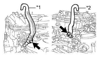
Text in Illustration *1 No. 1 Engine Hanger *2 No .2 Engine Hanger Remove the 2 bolts and 2 engine hangers.
-
-
INSTALL NO. 2 ENGINE MOUNTING STAY RH
-
Install the No. 2 engine mounting stay RH with the 2 bolts.
- Torque:
- 38 N*m { 387 kgf*cm, 28 ft.*lbf }
-
-
CONNECT STEERING INTERMEDIATE SHAFT ASSEMBLY
-
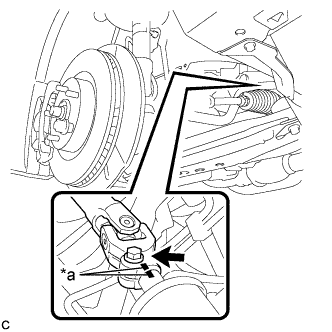
Text in Illustration *a Matchmark Align the matchmarks and install the steering intermediate shaft to the steering link assembly.
-
Install the bolt.
- Torque:
- 35 N*m { 360 kgf*cm, 26 ft.*lbf }
-
-
CONNECT NO. 5 INVERTER COOLING HOSE
-
Connect the No. 5 inverter cooling hose to the hybrid vehicle transaxle assembly and slide the clip to secure it.
-
-
CONNECT WIRE HARNESS
-
Connect the 3 clamps and install the motor cable to the hybrid vehicle transaxle assembly with the bolt.
- Torque:
- 8.0 N*m { 82 kgf*cm, 71 in.*lbf }
-
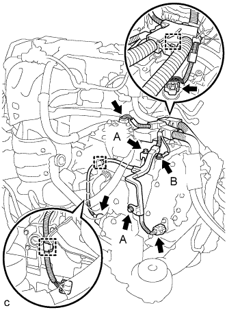
Connect the 3 clamps and 4 connectors, and install the wire harness to the hybrid vehicle transaxle assembly with the 3 bolts.
- Torque:
- Bolt (A)
- 8.0 N*m { 82 kgf*cm, 71 in.*lbf }
- Torque:
- Bolt (B)
- 12 N*m { 122 kgf*cm, 9 ft.*lbf }
-
-
CONNECT TRANSMISSION CONTROL CABLE ASSEMBLY
-
Connect the transmission control cable assembly to the 2 transmission control cable brackets.
-
Install a new clip to the No. 1 transmission control cable bracket.
-
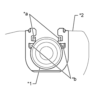
Text in Illustration *1 No. 1 Transmission Control Cable Assembly *2 No. 1 Transmission Control Cable Bracket *a Claw (A) *b Claw (B) Install the transmission control cable assembly to the No. 1 transmission control cable bracket.
Note
-
Make sure that the claws (A) on the clip are securely fit into the bracket holes.
-
Make sure that the cable is securely installed inside of the claws (B) of the clip.
-
-
Connect the transmission control cable assembly to the control shaft lever with the nut.
- Torque:
- 15 N*m { 148 kgf*cm, 11 ft.*lbf }
-
-
INSTALL NO. 1 ENGINE COVER SUB-ASSEMBLY
-
Engage the 3 pins and install the No. 1 engine cover sub-assembly.
-
-
INSTALL FRONT EXHAUST PIPE ASSEMBLY
-
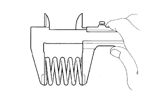
Using a vernier caliper, measure the free length of the compression spring.
Standard 42.0 mm (1.65 in.) Minimum 40.5 mm (1.60 in.) Tech Tips
If the length is less than the minimum, replace the compression spring.
-
Fully insert a new gasket to the exhaust manifold converter sub-assembly.
-
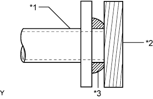
Text in Illustration *1 Exhaust Manifold Converter Sub-assembly *2 Wooden Block *3 Gasket Using a plastic hammer and wooden block, tap in the new gasket until its surface is flush with the exhaust manifold converter sub-assembly.
Note
-
Be sure to install the gasket in the correct direction.
-
Do not reuse the gasket.
-
Do not damage the gasket.
-
Do not push in the gasket by using the exhaust pipe when connecting it.
-
-
Install a new gasket to the front exhaust pipe assembly.
-
Connect the front exhaust pipe assembly to the exhaust pipe support.
-
Install the front exhaust pipe assembly with the 2 compression springs, 2 bolts and 2 nuts.
- Torque:
- 43 N*m { 438 kgf*cm, 32 ft.*lbf }
Tech Tips
After the installation, check that the gaps between the flanges of the exhaust manifold converter sub-assembly and front exhaust pipe assembly are consistent front-to-rear and left-to-right.
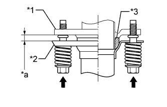
Text in Illustration *1 Exhaust Manifold Converter Sub-assembly *2 Front Exhaust Pipe Assembly *3 Gasket *a Space between flanges: 8.5 mm (0.335 in.) -
Connect the heated oxygen sensor connector.
-
-
INSTALL INVERTER TRAY BRACKET SUB-ASSEMBLY
-
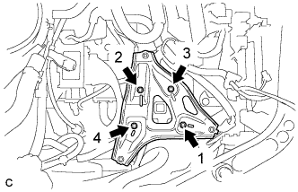
Temporarily install the inverter tray bracket sub-assembly to the body with the 4 bolts.
Tech Tips
Temporarily tighten bolt 1.
-
Install the 4 bolts in the order shown in the illustration.
- Torque:
- 8.0 N*m { 82 kgf*cm, 71 in.*lbf }
-
-
INSTALL INVERTER WITH CONVERTER ASSEMBLY
-
INSTALL FRONT DRIVE SHAFT HOLE SNAP RING LH
-
Install a new front drive shaft hole snap ring LH.
Note
Face the end gap of the front drive shaft hole snap ring downward.
-
-
INSTALL FRONT DRIVE SHAFT ASSEMBLY
-
ADD HYBRID TRANSAXLE FLUID
-
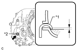
Text in Illustration *1 Filler Nozzle *2 Filler Plug Add transaxle fluid until the fluid level is between 0 to 5 mm (0 to 0.197 in.) from the bottom lip of the filler plug opening.
Note
-
Stop the vehicle on a level surface.
-
Use Toyota Genuine ATF WS.
-
Be sure to fully insert the filler nozzle into the filler plug opening.
-
Be sure to add fluid slowly. If fluid is added quickly, the fluid may hit internal parts and bounce back, resulting in fluid coming out of the filler plug opening.
-
Be sure to directly check that the transaxle fluid level is within the specified range.
-
Insufficient or excessive amounts of transaxle fluid may damage the hybrid transaxle.
Reference 3.7 liters (3.9 US qts, 3.2 Imp. qts) -
-
After adding fluid, leave it for 30 seconds so that the fluid surface can become still again, and then check that the fluid level is between 0 to 5 mm (0 to 0.197 in.) from the bottom lip of the filler plug opening. (If the fluid level is too low, return to the Add Hybrid Transaxle Fluid procedure.)
Note
After adding fluid, make sure to check the fluid level.
-
-
ADD COOLANT (for Inverter)
Note
-
Do not reuse the drained coolant because it may contain foreign objects.
-
If the vehicle is driven with air in the inverter cooling system, damage may occur and the following DTCs may be set.
DTC Code Detection Item P0A01-726 Motor Electronics Coolant Temperature Sensor Circuit Range / Performance P0A04-725 Motor Electronics Coolant Temperature Sensor Circuit Intermittent P0A08-264 DC / DC Converter Status Circuit P0A78-284 Drive Motor "A" Inverter Performance P0A78-286 Drive Motor "A" Inverter Performance P0A7A-322 Generator Inverter Performance P0A7A-324 Generator Inverter Performance P0A93-346 Inverter Cooling System Performance P0A94-553 DC / DC Converter Performance P0A94-557 DC / DC Converter Performance P0AEE-277 Motor Inverter Temperature Sensor "A" Circuit Range / Performance P0AF1-276 Drive Motor Inverter Temperature Sensor "A" Circuit Intermittent / Erratic P0BCD-315 Generator Inverter Temperature Sensor Circuit Range / Performance P0BD0-314 Generator Inverter Temperature Sensor Circuit Intermittent / Erratic P0C39-626 DC / DC Converter Temperature Sensor "A" Range / Performance P0C3C-625 DC / DC Converter Temperature Sensor "A" Intermittent / Erratic P0C3E-628 DC / DC Converter Temperature Sensor "B" Range / Performance P0C41-627 DC / DC Converter Temperature Sensor "B" Intermittent / Erratic P0C73-776 Motor Electronics Coolant Pump "A" Control Performance
-
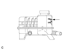
Slowly pour coolant into the reserve tank until it reaches the FULL line.
Coolant quantity 3.2 liters (3.4 US qts, 2.8 Imp. qts.) Note
To prevent foreign matter such as dust or dirt from entering the cooling system, make sure to confirm that the container used to add coolant is clean and free of foreign matter such as dust or dirt.
-
When using the Techstream:
-
Connect the Techstream to the DLC3.
-
Turn the power switch on (IG).
-
Enter the following menus: Powertrain / Hybrid Control / Active Test / Activate the Water Pump.
-
Keep the coolant at the FULL line in the reserve tank to compensate for the drop in coolant level when the air bleeds.
Standard Air bleeding from the inverter cooling system is completed when the noise made by the inverter water pump assembly becomes smaller and the circulation of coolant in the reserve tank improves. Tech Tips
-
If free spinning of the inverter water pump is detected for approximately 5 seconds, failsafe control will be activated to suspend the operation of the pump for approximately 15 seconds and resume operation for approximately 4 seconds repeatedly. Operation of the inverter water pump will return to normal if coolant is added.
-
Loud noise made by the inverter water pump assembly and poor circulation of coolant in the reserve tank indicates that there is air in the cooling system.
Tech Tips
Loud noise made by the water pump and poor circulation of coolant in the reserve tank indicates that there is air in the cooling system.
-
-
-
When not using the Techstream:
-
Turn the power switch on (READY).[*1]
-
Turn the power switch off and add coolant to the FULL line because the coolant level drops as the air bleeds.[*2]
Note
-
Be sure to turn the power switch off before adding SLLC.
-
Do not work on the components in the engine compartment while the vehicle is in the READY-on state because the engine is in intermittent operation.
-
-
Repeat steps [*1] and [*2] until air bleeding from the cooling system is completed.
Standard Air bleeding from the inverter cooling system is completed when the noise made by the inverter water pump assembly becomes smaller and the circulation of coolant in the reserve tank improves. Tech Tips
Loud noise made by the water pump and poor circulation of coolant in the reserve tank indicates that there is air in the cooling system.
-
-
After the air is completely bled from the cooling system, tighten the reserve tank cap.
-
Add coolant to the FULL line of the reserve tank.
-
-
INSPECT HYBRID TRANSAXLE FLUID
-
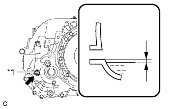
Text in Illustration *1 Filler Plug Using a 10 mm hexagon socket wrench, remove the filler plug and gasket.
-
Check that the fluid level is between 0 to 5 mm (0 to 0.197 in.) from the bottom lip of the filler plug opening. (If the fluid level is too low, return to the Add Hybrid Transaxle Fluid procedure.)
Note
-
Stop the vehicle on a level surface.
-
Be sure to directly check that the transaxle fluid level is within the specified range.
-
Insufficient or excessive amounts of transaxle fluid may damage the hybrid transaxle.
-
If the fluid was replaced or fluid was added, make sure to recheck the fluid level after driving the vehicle.
-
-
Check for leaks if the quantity of transaxle fluid is low. (If there are no fluid leaks but the amount of the fluid is insufficient, add fluid Click here.
-
Using a 10 mm hexagon socket wrench, install the filler plug with a new gasket.
- Torque:
- 39 N*m { 400 kgf*cm, 29 ft.*lbf }
-
-
INSPECT FOR OIL LEAK
-
INSPECT FOR COOLANT LEAK (for Inverter)
-
Remove the reserve tank cap.
CAUTION:
To avoid the danger of being burned, do not remove the reserve tank cap while the coolant for the inverter is still hot.
-
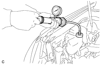
Install the radiator cap tester.
-
Pump the radiator cap tester to 122 kPa (1.2 kgf/ cm2, 17 psi), and then check that the pressure does not drop.
Tech Tips
If the pressure drops, check the hoses, radiator, water pump, inverter with converter, and hybrid vehicle transaxle assembly for leaks.
-
Reinstall the reserve tank cap.
-
-
INSPECT FOR EXHAUST GAS LEAK
-
INSTALL FRONT FENDER APRON SEAL LH
-
INSTALL FRONT FENDER APRON SEAL RH
-
INSTALL ENGINE UNDER COVER LH
-
INSTALL FRONT WHEEL OPENING EXTENSION PAD LH
-
INSTALL ENGINE UNDER COVER RH
-
INSTALL FRONT WHEEL OPENING EXTENSION PAD RH
-
INSPECT AND ADJUST FRONT WHEEL ALIGNMENT
-
CHECK FOR SPEED SENSOR SIGNAL