HYBRID VEHICLE TRANSAXLE (When Using the Engine Support Bridge) REMOVAL

-
ALIGN FRONT WHEELS FACING STRAIGHT AHEAD
-
SECURE STEERING WHEEL
-
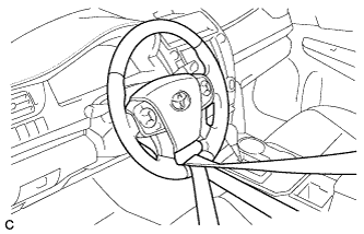
Secure the steering wheel with the seat belt in order to prevent rotation.
Tech Tips
This operation is useful to prevent damage to the spiral cable.
-
-
REMOVE FRONT WHEEL OPENING EXTENSION PAD RH
-
REMOVE ENGINE UNDER COVER RH
-
REMOVE FRONT WHEEL OPENING EXTENSION PAD LH
-
REMOVE ENGINE UNDER COVER LH
-
REMOVE FRONT FENDER APRON SEAL LH
-
REMOVE FRONT FENDER APRON SEAL RH
-
DRAIN HYBRID TRANSAXLE FLUID
-
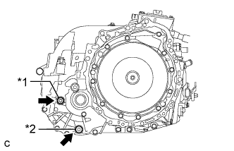
Text in Illustration *1 Filler Plug *2 Drain Plug Using a 10 mm hexagon socket wrench, remove the filler plug and gasket.
-
Using a 10 mm hexagon socket wrench, remove the drain plug and gasket to drain the hybrid transaxle fluid.
-
Using a 10 mm hexagon socket wrench, install the drain plug and a new gasket.
- Torque:
- 39 N*m { 400 kgf*cm, 29 ft.*lbf }
-
-
DRAIN COOLANT (for Inverter)
Note
-
Do not reuse the drained coolant because it may contain foreign objects.
-
Collect the drained coolant and measure its volume to establish a benchmark. When adding coolant, make sure to add more coolant than the measured amount.
-
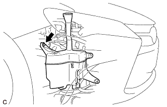
Remove the reserve tank cap.
CAUTION:
To avoid the danger of being burned, do not remove the reserve tank cap while the coolant for the inverter is still hot.
-
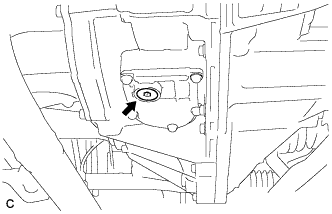
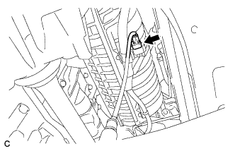
Using a hexagon wrench (10 mm), remove the drain plug indicated in the illustration and drain the coolant.
CAUTION:
Use caution when handling coolant immediately after driving or in summer because it may be hot.
-
Install the plug with a new gasket.
- Torque:
- 39 N*m { 397 kgf*cm, 29 ft.*lbf }
-
-
REMOVE FRONT DRIVE SHAFT ASSEMBLY
-
REMOVE INVERTER WITH CONVERTER ASSEMBLY
-
REMOVE INVERTER TRAY BRACKET SUB-ASSEMBLY
-
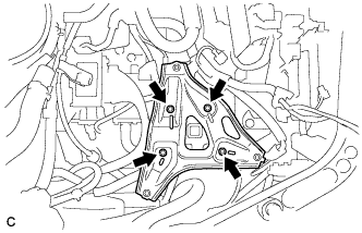
Remove the 4 bolts and inverter tray bracket sub-assembly from the body.
-
-
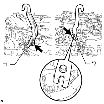
REMOVE FRONT EXHAUST PIPE ASSEMBLY
-
Disconnect the heated oxygen sensor connector.
-
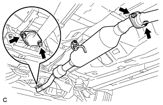
Remove the 2 bolts, 2 compression springs and 2 nuts.
-
Remove the front exhaust pipe assembly from the exhaust pipe support.
-
Remove the 2 gaskets from the exhaust manifold converter sub-assembly and front exhaust pipe assembly.
-
-
REMOVE NO. 1 ENGINE COVER SUB-ASSEMBLY
-
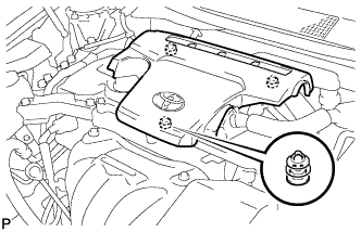
Lift the rear of the No. 1 engine cover sub-assembly to detach the No. 1 engine cover sub-assembly from the 2 pins, and then lift the front of the No. 1 engine cover sub-assembly to detach the No. 1 engine cover sub-assembly from the pin and remove the No. 1 engine cover sub-assembly.
Note
Attempting to disengage both front and rear pins at the same time may cause the No. 1 engine cover sub-assembly to break.
-
-
DISCONNECT TRANSMISSION CONTROL CABLE ASSEMBLY
-
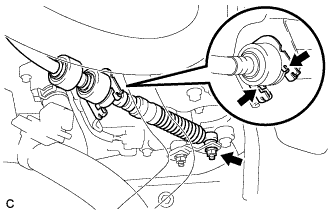
Remove the nut and disconnect the transmission control cable assembly from the control shaft lever.
-
Using a screwdriver, disengage the 4 claws and disconnect the transmission control cable assembly with clip from the No. 1 transmission control cable bracket.
-
Remove the clip from the transmission control cable assembly.
-
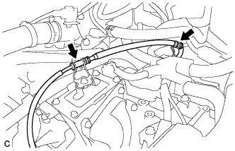
Disconnect the transmission control cable assembly from the 2 transmission control brackets.
-
-
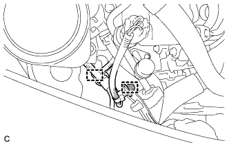
DISCONNECT WIRE HARNESS
-
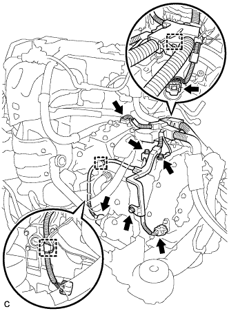
Remove the 3 bolts and disconnect the 4 connectors, 3 clamps and wire harness from the hybrid vehicle transaxle assembly.
-
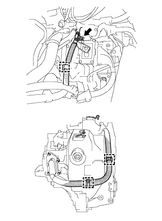
Remove the bolt and disconnect the 3 clamps and motor cable from the hybrid vehicle transaxle assembly.
-
-
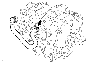
DISCONNECT NO. 5 INVERTER COOLING HOSE
-
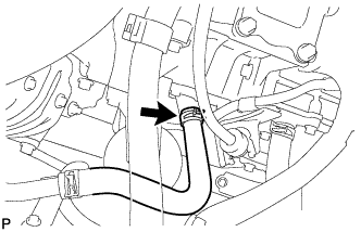
Slide the clip and disconnect the No. 5 inverter cooling hose from the hybrid vehicle transaxle assembly.
-
-
SEPARATE STEERING INTERMEDIATE SHAFT ASSEMBLY
-
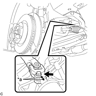
Text in Illustration *a Matchmark Put matchmarks on the steering intermediate shaft assembly and steering link assembly.
-
Remove the bolt.
-
Separate the steering intermediate shaft assembly from the steering link assembly.
-
-
REMOVE NO. 2 ENGINE MOUNTING STAY RH
-
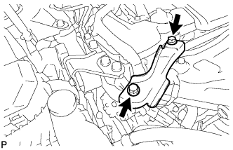
Remove the 2 bolts and No. 2 engine mounting stay RH.
-
-
INSTALL ENGINE HANGERS
-
Install the 2 engine hangers with the 4 bolts as shown in the illustration.
Part No. Item Part No. No. 1 Engine Hanger 12281-36020 No. 2 Engine Hanger 12282-36021 Bolt 91552-81040 or 91552-81025 - Torque:
- 43 N*m { 438 kgf*cm, 32 ft.*lbf }
-
Attach an engine sling device and hang the engine with a chain block.
-
-
INSTALL ENGINE SUPPORT BRIDGE
-
Disengage the 2 clamps.
-
Remove the 2 hood support assemblies Click here.
-
Install SST to the vehicle body as shown in the illustration.
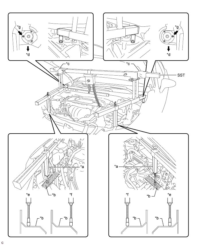
Text in Illustration *a Support Shaft *b Side Member *c Cloth *d Front Side *e Correct *f Incorrect *g Front Suspension Nut - - - SST
- 09940-10020
CAUTION:
Make sure the fuse bolt is not deformed.
Text in Illustration *a Fuse Bolt *b Correct *c Incorrect Note
-
Prevent SST from contacting the vehicle body or windshield.
-
To prevent damage to the engine hood, place pieces of cloth between the engine hood and SST.
-
Lightly shake SST by hand to make sure it is securely installed while performing work.
-
Set the support shafts on level surfaces.
-
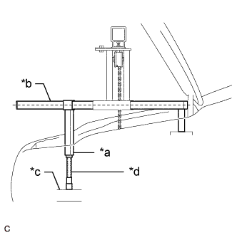
Text in Illustration *a Support Shaft *b Sub Beam *c Side Member *d Threaded Portion Turn the threaded portion of each support shaft to adjust its height and make the SST sub beams parallel to the ground.
-
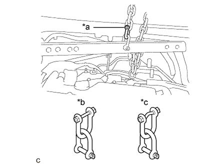
Connect the chain to the division bar with the shackle at the position shown in the illustration.
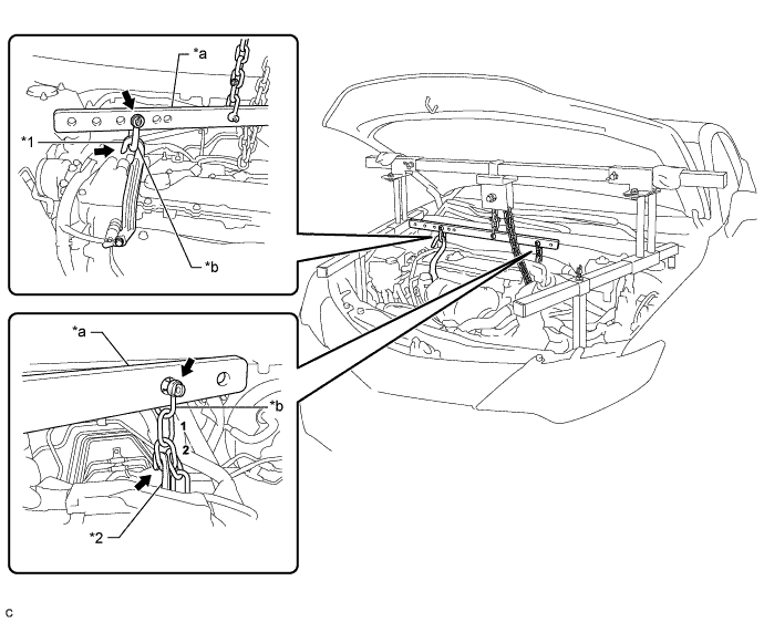
Text in Illustration *1 No. 1 Engine Hanger *2 No. 2 Engine Hanger *a Division Bar *b Shackle -
Connect the division bar and No. 1 engine hanger with the shackle.
-
Connect the 2nd link of the chain to the No. 2 engine hanger.
-
Make sure the distance between the chain block assembly and division bar is 50 mm (1.97 in.) or more.
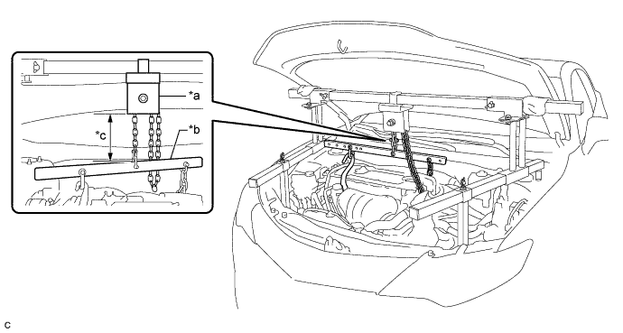
Text in Illustration *a Chain Block Assembly *b Division Bar *c 50 mm (1.97 in.) or more - - -
Adjust the position of the chain block assembly so that the chain is perpendicular to the SST main beam and sub beams as shown in the illustration.
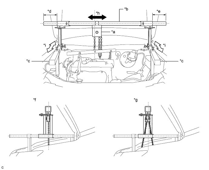
Text in Illustration *a Chain Block Assembly *b Main Beam *c Sub Beam *d Dimension (A) *e Dimension (B) *f Correct *g Incorrect *h Right to Left Adjustment *i Front to Rear Adjustment - - CAUTION:
To prevent the engine assembly with hybrid vehicle transaxle assembly from falling, make sure that the dimension (A) and dimension (B) are equal.
-
Tighten the 6 wing bolts and 2 bolts.
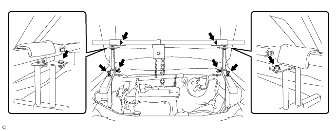
- Torque:
- for Bolt
- 30 N*m { 306 kgf*cm, 22 ft.*lbf }
-
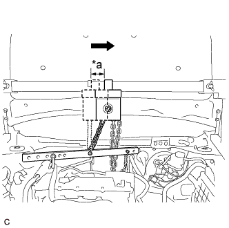
Text in Illustration *a Approximately 50 mm (1.97 in.) Move the chain block assembly approximately 50 mm (1.97 in.) as shown in the illustration.
-
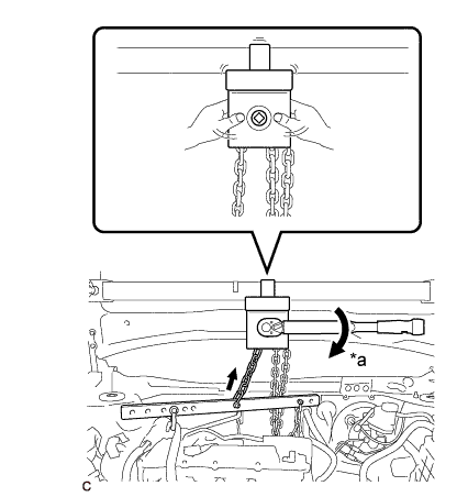
Text in Illustration *a Turn Tighten the chain block assembly until it cannot be moved any further by hand.
Note
-
When suspending the engine assembly with hybrid vehicle transaxle assembly, do not tighten the chain block assembly more than 50 N*m (510 kgf*cm, 37 ft.*lbf).
-
Do not shake the engine assembly with hybrid vehicle transaxle assembly excessively while it is being suspended.
-
-
-
INSTALL BELT
-
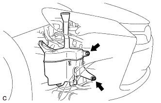
Remove the bolt and nut.
-
Loosen the bolt and disconnect the windshield washer jar assembly from the vehicle body.
Note
Do not remove the bolt.
-
Install SST to the vehicle body as shown in the illustration.
- SST
- 09727-00110
-
Using the SST ratchet buckle, tighten the SST belt until there is no slack.
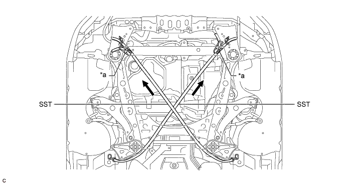
Text in Illustration *a Ratchet Buckle - -
-
-
REMOVE FRONT FRAME ASSEMBLY
-
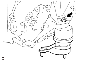
REMOVE ENGINE MOUNTING INSULATOR RH
-
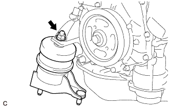
Remove the nut and engine mounting insulator RH from the engine mounting bracket RH.
-
-
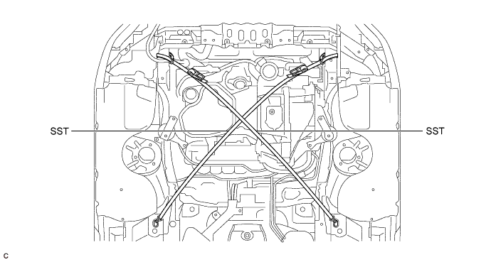
INSTALL SUPPORT BAR
-
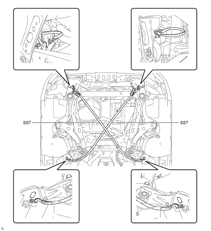
Install the SST (support bar) to the vehicle body with the 2 bolts as shown in the illustration.
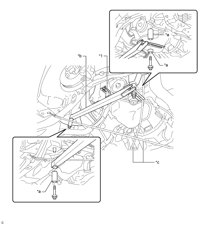
Text in Illustration *1 Engine Mounting Bracket RH - - *a Spacer *b SST (Support Bar) *c SST (Belt) - - - SST
- 09944-10020
CAUTION:
To prevent the engine assembly with hybrid vehicle transaxle assembly from falling while servicing, do not remove SST (belt).
-
Install the bolt to the engine mounting bracket RH.
-
-
REMOVE FRONT ENGINE MOUNTING INSULATOR
-
Remove the bolt and front engine mounting insulator from the front engine mounting bracket.
-
-
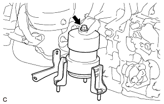
REMOVE ENGINE MOUNTING INSULATOR LH
-
Remove the nut and engine mounting insulator LH from the hybrid vehicle transaxle assembly.
-
-
SUPPORT ENGINE ASSEMBLY
-
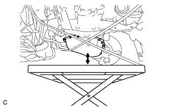
Set an engine lifter.
CAUTION:
To prevent the engine assembly with hybrid vehicle transaxle assembly from falling while servicing, do not remove SST.
Note
Make sure that there is a clearance between the oil pan sub-assembly and engine lifter.
-
-
REMOVE BELT
-
Remove SST from the vehicle body.
-
-
REMOVE HYBRID VEHICLE TRANSAXLE ASSEMBLY
-
Using a transmission jack attachment, set the hybrid vehicle transaxle assembly on a transmission jack.
Note
-
Secure the hybrid vehicle transaxle assembly to the transmission jack using a suitable adapter, such as a rope or attachment.
-
To prevent the motor water jacket cover assembly from deforming, do not place any attachments under the motor water jacket cover assembly of the hybrid vehicle transaxle assembly.
-
-
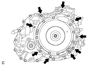
Remove the 9 bolts and hybrid vehicle transaxle assembly from the engine assembly.
Note
-
To avoid damage to the 2 knock pins, do not pry between the hybrid vehicle transaxle assembly and engine assembly.
-
To prevent the splines of the transmission input damper assembly from becoming misaligned, do not allow the hybrid vehicle transaxle assembly to hit the transmission input damper assembly during hybrid vehicle transaxle assembly removal and installation.
-
Secure the hybrid vehicle transaxle assembly to the transmission jack using a belt, etc. to prevent it from falling.
-
-
-
REMOVE FRONT ENGINE MOUNTING BRACKET
-
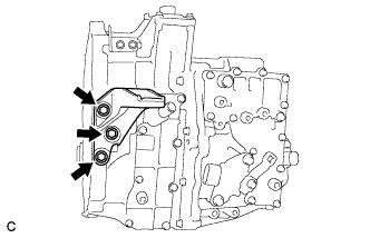
Remove the 3 bolts and front engine mounting bracket from the hybrid vehicle transaxle assembly.
-
-
REMOVE NO. 1 TRANSMISSION CONTROL CABLE BRACKET
-
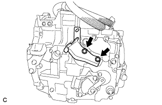
Remove the 2 bolts and No. 1 transmission control cable bracket from the hybrid vehicle transaxle assembly.
-
-
REMOVE NO. 2 TRANSMISSION CONTROL CABLE BRACKET
-
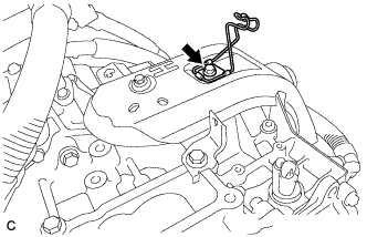
Remove the bolt and No. 2 transmission control cable bracket from the hybrid vehicle transaxle assembly.
-
-
REMOVE NO. 3 TRANSMISSION CONTROL CABLE BRACKET
-
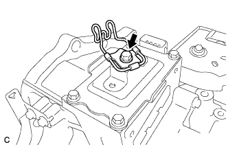
Remove the bolt and No. 3 transmission control cable bracket from the hybrid vehicle transaxle assembly.
-
-
REMOVE AUTOMATIC TRANSMISSION CASE COVER
-
Disengage the 2 guides and remove the automatic transmission case cover from the No. 3 automatic transmission case cover.
-
-
REMOVE NO. 3 AUTOMATIC TRANSMISSION CASE COVER
-
Remove the 2 bolts, clip and No. 3 automatic transmission case cover from the hybrid vehicle transaxle assembly.
-
-
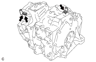
REMOVE HYBRID TRANSAXLE MASS DAMPER
-
Remove the hybrid transaxle mass damper and gasket from the hybrid vehicle transaxle assembly.
-
-
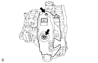
REMOVE WIRE HARNESS CLAMP BRACKET
-
Remove the 3 bolts and 2 wire harness clamp brackets from the hybrid vehicle transaxle assembly.
-
-
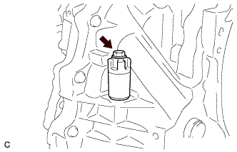
REMOVE NO. 1 INVERTER COOLING HOSE ASSEMBLY
-
Remove the No. 1 inverter cooling hose assembly from the hybrid vehicle transaxle assembly.
-
-
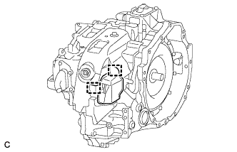
REMOVE WITH HEAD STRAIGHT SCREW PLUG
Tech Tips
Perform this procedure only when replacement of the with head straight screw plug is necessary.
-
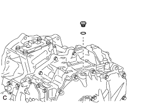
Using a 10 mm hexagon socket wrench, remove the with head straight screw plug and O-ring from the hybrid vehicle transaxle assembly.
-