POWER SWITCH INSTALLATION

-
INSTALL POWER SWITCH
-
Engage the 2 claws to install the power switch.
-
-
INSTALL LOWER INSTRUMENT PANEL FINISH PANEL ASSEMBLY
-
Connect the connector.
-
Engage the 4 clips and guide to install the lower instrument panel finish panel assembly.
-
-
INSTALL LOWER NO. 1 INSTRUMENT PANEL FINISH PANEL ASSEMBLY
-
Engage the 4 claws, 9 clips and 3 guides.
-
Install the lower No. 1 instrument panel finish panel assembly with the bolt <B> and screw <C> or <D>.
-
-
INSTALL FRONT PANEL GARNISH LH
-
Remove the protective cover.
-
Make sure that the front pillar garnish clip is not damaged.
Note
If there is any damage, replace the garnish clip with a new one.
-
Install the front pillar garnish clip to front pillar garnish LH.
Tech Tips
Install the front pillar garnish clip so that it faces as shown in the illustration.
-
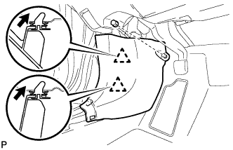
Engage the 2 guides as shown in the illustration.
-
Engage the 2 clips to install the front pillar garnish LH.
-
-
CONNECT HOOD LOCK CONTROL LEVER SUB-ASSEMBLY
-
Engage the claw and 2 guides to connect the hood lock control lever sub-assembly.
-
-
INSTALL INSTRUMENT CLUSTER FINISH PANEL ASSEMBLY
-
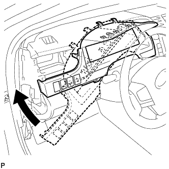
Temporarily install the instrument cluster finish panel assembly as shown in the illustration.
-
Connect each connector.
-
Engage the 5 claws, 5 clips and 2 guides, and install the instrument cluster finish panel assembly.
-
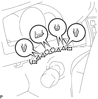
Engage the 2 claws, 4 clips and 2 guides.
-
-
INSTALL NO. 1 INSTRUMENT PANEL REGISTER ASSEMBLY
-
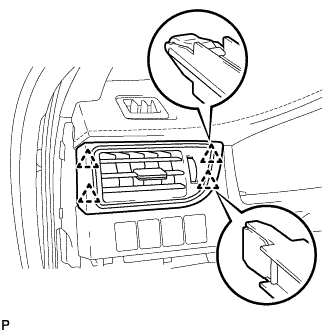
Engage the 4 clips to install the No. 1 instrument panel register assembly.
-
-
INSTALL NO. 1 INSTRUMENT CLUSTER FINISH PANEL GARNISH
-
Engage the 3 clips to install the No. 1 instrument cluster finish panel garnish.
-
-
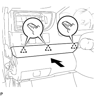
INSTALL INSTRUMENT SIDE PANEL LH
-
Engage the 3 guides.
-
Engage the 4 claws to install the instrument side panel LH as shown in the illustration.
-
-
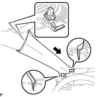
INSTALL FRONT DOOR OPENING TRIM WEATHERSTRIP LH
-
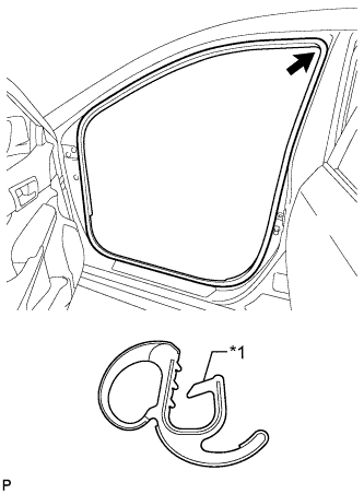
Text in Illustration *1 Alignment Mark (Yellow) Align the alignment mark (Yellow) on the weatherstrip with the protruding portion on the body indicated by the arrow in the illustration, and install the front door opening trim weatherstrip LH.
Note
After installation, check that the corners fit correctly.
-
-
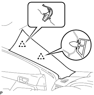
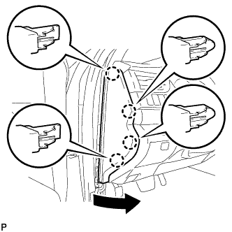
INSTALL COWL SIDE TRIM SUB-ASSEMBLY LH
-
Insert the 2 clips in the direction indicated by the arrows shown in the illustration to engage them.
-
Install the cowl side trim sub-assembly LH with the clip.
-
-
INSTALL FRONT DOOR SCUFF PLATE LH
-
Engage the 10 claws to install the front door scuff plate LH.
-
-
INSTALL NAVIGATION RECEIVER ASSEMBLY WITH AIR CONDITIONING CONTROL ASSEMBLY
-
INSTALL RADIO RECEIVER ASSEMBLY WITH AIR CONDITIONING CONTROL ASSEMBLY
-
CONNECT CABLE TO AUXILIARY BATTERY NEGATIVE TERMINAL
Note
When disconnecting the cable, some systems need to be initialized after the cable is reconnected Click here.
-
INSTALL LUGGAGE TRIM SERVICE HOLE COVER
-
Engage the claw to connect the luggage trim service hole cover.
-