POWER SWITCH REMOVAL

-
PRECAUTION
Note
After turning the power switch off, waiting time may be required before disconnecting the cable from the negative (-) auxiliary battery terminal. Therefore, make sure to read the disconnecting the cable from the negative (-) auxiliary battery terminal notices before proceeding with work Click here.
-
REMOVE LUGGAGE TRIM SERVICE HOLE COVER
-
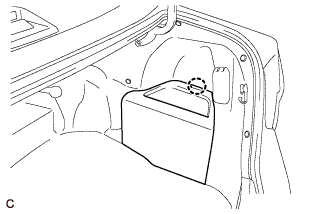
Disengage the claw to remove the luggage trim service hole cover.
-
-
DISCONNECT CABLE FROM AUXILIARY BATTERY NEGATIVE TERMINAL
Note
When disconnecting the cable, some systems need to be initialized after the cable is reconnected Click here.
-
REMOVE RADIO RECEIVER ASSEMBLY WITH AIR CONDITIONING CONTROL ASSEMBLY
-
REMOVE NAVIGATION RECEIVER ASSEMBLY WITH AIR CONDITIONING CONTROL ASSEMBLY
-
REMOVE FRONT DOOR SCUFF PLATE LH
-
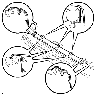
Disengage the 10 claws and remove the front door scuff plate LH.
-
-
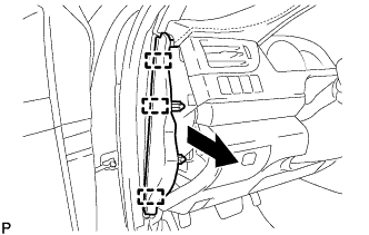
REMOVE COWL SIDE TRIM SUB-ASSEMBLY LH
-
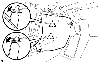
Remove the clip.
-
Pull the cowl side trim sub-assembly LH in the direction indicated by the arrow shown in the illustration to disengage the 2 clips and remove the cowl side trim sub-assembly LH.
-
-
DISCONNECT FRONT DOOR OPENING TRIM WEATHERSTRIP LH
-
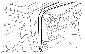
Disconnect the front door opening trim weatherstrip LH.
-
-
REMOVE INSTRUMENT SIDE PANEL LH
-
Using a moulding remover, disengage the 4 claws as shown in the illustration.
-
Disengage the 3 guides and remove the instrument side panel LH as shown in the illustration.
-
-
REMOVE NO. 1 INSTRUMENT CLUSTER FINISH PANEL GARNISH
-
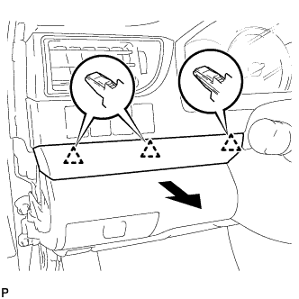
Disengage the 3 clips to remove the No. 1 instrument cluster finish panel garnish as shown in the illustration.
-
-
REMOVE NO. 1 INSTRUMENT PANEL REGISTER ASSEMBLY
-
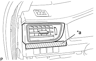
Text in Illustration *a Protective Tape Apply protective tape to the area shown in the illustration.
-
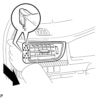
Disengage the 2 clips as shown in the illustration.
-
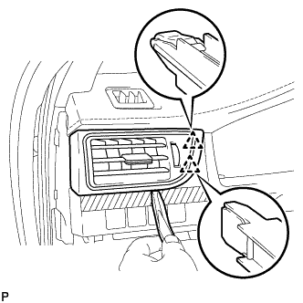
Using a moulding remover, disengage the 2 clips to remove the No. 1 instrument panel register assembly.
-
-
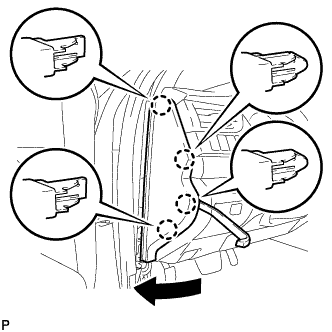
REMOVE INSTRUMENT CLUSTER FINISH PANEL ASSEMBLY
-
Operate the tilt and telescopic lever to fully extend and lower the steering column assembly.
-
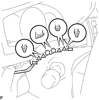
Using a moulding remover, disengage the 2 claws, 4 clips and 2 guides.
-
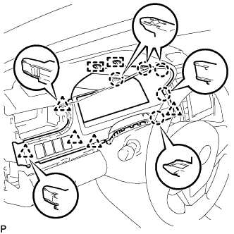
Disengage the 5 claws, 5 clips and 2 guides.
-
Disconnect each connector.
-
Remove the instrument cluster finish panel assembly as shown in the illustration.
-
-
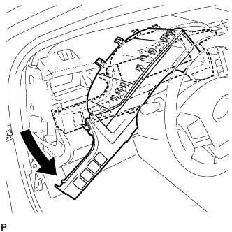
REMOVE FRONT PANEL GARNISH LH
-
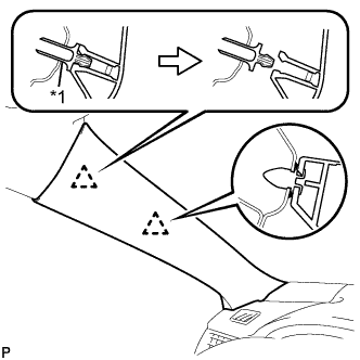
Text in Illustration *1 Front Pillar Garnish Clip Pull the upper part of the garnish toward the inside of the cabin and disengage the garnish from the base of the 2 clips.
Tech Tips
Make the front pillar garnish LH hang down from the front pillar garnish clip.
-
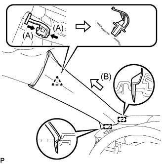
While pushing the tabs on the front pillar garnish clip in the direction indicated by the arrow (A) shown in the illustration, disengage the front pillar garnish clip.
Note
Do not apply excessive force using a tool.
-
Pull the garnish in the direction indicated by the arrow (B) shown in the illustration to disengage the 2 guides and remove the front pillar garnish LH.
-
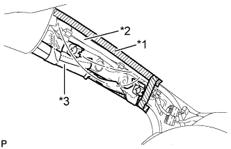
Text in Illustration *1 Adhesive Tape *2 Protective Cover *3 Curtain Shield Airbag Assembly Protect the curtain shield airbag assembly.
-
Cover the airbag with a piece of cloth or nylon and secure the edges of the cover with tape as shown in the illustration.
Note
Cover the curtain shield airbag with a protective cover as soon as the front pillar garnish is removed.
-
-
-
DISCONNECT HOOD LOCK CONTROL LEVER SUB-ASSEMBLY
-
Disengage the claw and 2 guides to disconnect the hood lock control lever sub-assembly.
-
-
REMOVE LOWER NO. 1 INSTRUMENT PANEL FINISH PANEL ASSEMBLY
-
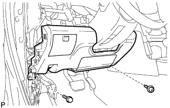
Remove the bolt <C> and screw <D> or <E>.
-
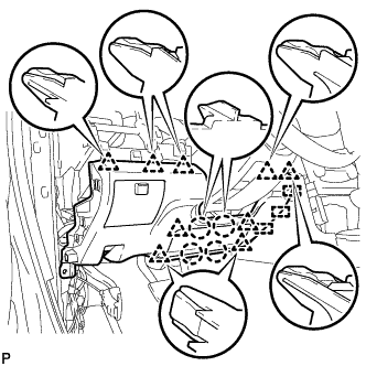
Disengage the 4 claws, 9 clips and 3 guides to remove the lower No. 1 instrument panel finish panel assembly.
-
-
REMOVE LOWER INSTRUMENT PANEL FINISH PANEL ASSEMBLY
-
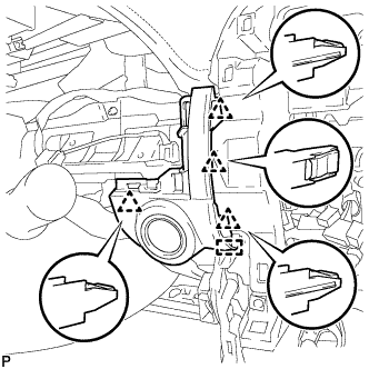
Disengage the 4 clips and guide.
-
Disconnect the connector and remove the lower instrument panel finish panel assembly.
-
-
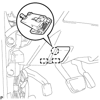
REMOVE POWER SWITCH
-
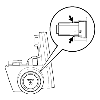
Disengage the 2 claws and remove the power switch.
-