DYNAMIC RADAR CRUISE CONTROL SYSTEM, Diagnostic DTC:C1A05

| DTC Code | DTC Name |
|---|---|
| C1A05 | Stop Light Switch Circuit |
DESCRIPTION
When the brake pedal is depressed, the stop light switch assembly sends a brake pedal operation signal to the driving support ECU assembly. After reception of this signal, the driving support ECU assembly cancels the dynamic radar cruise control system. When the driving support ECU assembly detects a problem in the stop light switch assembly circuit, DTC C1A05 is stored.
| DTC No. | DTC Detection Condition | Trouble Area |
|---|---|---|
| C1A05 | When the power switch is on (IG) or the cruise control main switch (ON-OFF button) is on, the driving support ECU assembly detects a malfunction in the signal received from the stop light switch assembly. |
|
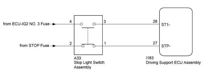
WIRING DIAGRAM
INSPECTION PROCEDURE
Note
-
Inspect the fuses for circuits related to this system before performing the following inspection procedure.
-
When replacing the driving support ECU assembly, always replace it with a new one. If a driving support ECU assembly which was installed to another vehicle is used, the information stored in the driving support ECU assembly will not match the information from the vehicle. As a result, a DTC may be stored.
PROCEDURE
-
CHECK HARNESS AND CONNECTOR (POWER SOURCE)
-
Disconnect the A33 stop light switch assembly connector.
-
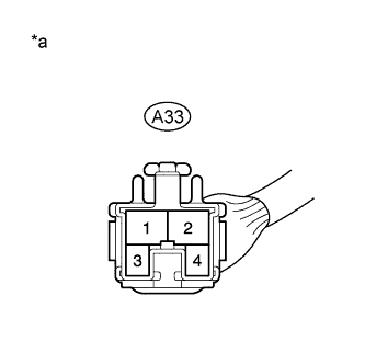
Text in Illustration *a Front view of wire harness connector
(to Stop Light Switch Assembly)
Measure the voltage according to the value(s) in the table below.
Standard Voltage Tester Connection Condition Specified Condition A33-4 - Body ground Power switch off 11 to 14 V A33-2 - Body ground Power switch on (IG) 11 to 14 V -
Turn the power switch off
-
Reconnect the A33 stop light switch assembly connector.
NG 
REPAIR OR REPLACE HARNESS OR CONNECTOR
OK 
-
-
INSPECT STOP LIGHT SWITCH ASSEMBLY
-
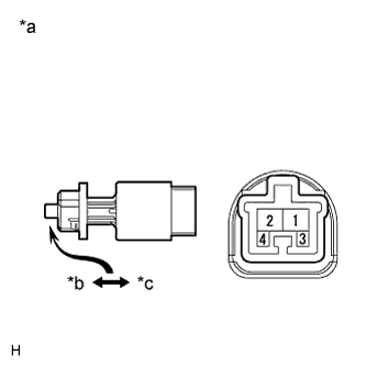
Text in Illustration *a Component without harness connected
(Stop Light Switch Assembly)
*b Not pushed *c Pushed Remove the stop light switch assembly Click here.
-
Measure the resistance according to the value(s) in the table below.
Standard Resistance Tester Connection Condition Specified Condition 1 - 2 Switch pin not pushed Below 0.1 Ω 3 - 4 Switch pin not pushed 10 kΩ or higher 1 - 2 Switch pin pushed 10 kΩ or higher 3 - 4 Switch pin pushed Below 200 Ω
NG
REPLACE STOP LIGHT SWITCH ASSEMBLY Click here
OK
-
-
CHECK HARNESS AND CONNECTOR (STOP LIGHT SWITCH ASSEMBLY - DRIVING SUPPORT ECU ASSEMBLY)
-
Disconnect the A33 stop light switch assembly connector.
-
Disconnect the I183 driving support ECU assembly connector.
-
Measure the resistance according to the value(s) in the table below.
Standard Resistance (Check for Open) Tester Connection Condition Specified Condition A33-3 - I183-28 (ST1-) Always Below 1 Ω A33-1 - I183-27 (STP-) Always Below 1 Ω Standard Resistance (Check for Open) Tester Connection Condition Specified Condition A33-3 or I183-28 (ST1-) - Body ground Always 10 kΩ or higher A33-1 or I183-27 (STP-) - Body ground Always 10 kΩ or higher -
Reconnect the A33 stop light switch assembly connector.
-
Reconnect the I183 driving support ECU assembly connector.
NG
REPAIR OR REPLACE HARNESS OR CONNECTOR
OK 
REPLACE DRIVING SUPPORT ECU ASSEMBLY Click here
-