HYBRID BATTERY SYSTEM, Diagnostic DTC:P0A7F-123

| DTC Code | DTC Name |
|---|---|
| P0A7F-123 | Hybrid Battery Pack Deterioration |
DESCRIPTION
-
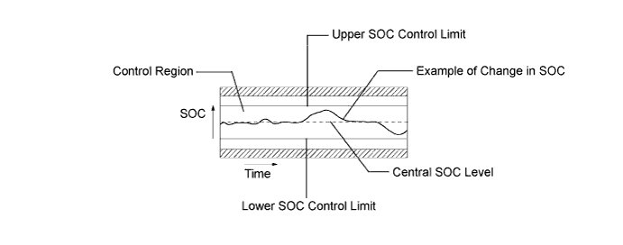
The battery smart unit and the power management control ECU calculate the SOC (state of charge) of the HV battery through the accumulated amperage in the HV battery. The battery smart unit sends the condition of the HV battery to the power management control ECU. Then the power management control ECU calculates the SOC based on the information and controls HV battery charge and discharge according to the driving condition.
DTC No. INF Code DTC Detection Condition Trouble Area P0A7F 123
-
Internal resistance of the HV battery is higher than the standard (1 trip detection)
-
Difference in the capacity between battery blocks is larger than the standard (2 trip detection)
-
HV battery
-
Battery smart unit
Tech Tips
P0A7F-123 will not be set unless the vehicle is driven for approximately 10 minutes after clearing the DTC. (As 2 trip detection logic is used, check for DTCs including pending DTCs.)
-
MONITOR DESCRIPTION
-
The battery smart unit calculates the resistance of the HV battery through amperage and voltage, and uses this resistance to determine the extent of deterioration of the HV battery. If the battery smart unit detects that the resistance of the HV battery has exceeded the standard, it determines that a malfunction has occurred. In addition, the battery smart unit monitors the SOC, and if the difference between the maximum and minimum SOC values exceeds the standard, it determines that a malfunction has occurred. When either of the malfunction detection conditions is met, the power management control ECU illuminates the MIL and set a DTC.
MONITOR STRATEGY
| Related DTCs | P0A7F (INF 123): Battery cell malfunction |
| Required sensors / components | Main: Battery voltage sensor inside battery smart unit, battery current sensor Sub: Battery temperature sensor |
| Frequency of operation | Continuous |
| Duration | TMC's intellectual property |
| MIL operation | TMC's intellectual property |
| Sequence of operation | None |
TYPICAL ENABLING CONDITIONS
| The monitor will run whenever the following DTCs are not present | TMC's intellectual property |
| Other conditions belong to TMC's intellectual property | - |
TYPICAL MALFUNCTION THRESHOLDS
| TMC's intellectual property | - |
COMPONENT OPERATING RANGE
| Battery smart unit | DTC P0A7F (INF 123) is not detected |
CONFIRMATION DRIVING PATTERN
-
Connect the Techstream to the DLC3.
-
Turn the power switch on (IG) and turn the Techstream on.
-
Clear the DTCs (even if no DTCs are stored, perform the clear DTC procedure).
-
Turn the power switch off.
-
Turn the power switch on (READY) and turn the Techstream on.
-
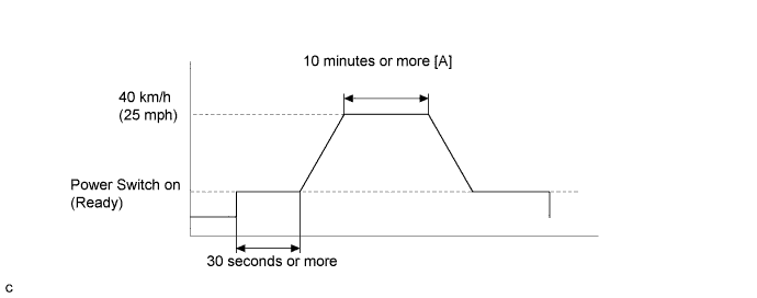
Turn the power switch on (READY) and wait for 30 seconds or more.
-
Drive the vehicle on urban roads at a speed of 40 km/h (25 mph) or more for a total of at least 10 minutes. [A]
Note
Avoid abrupt acceleration or braking.
-
Enter the following menus: Powertrain / Hybrid Control / Trouble Codes.
-
Check that permanent DTCs are cleared.
-
If the permanent DTCs are not cleared, perform the universal trip, and then check for permanent DTCs again.
Tech Tips
-
If a permanent DTC is output, the system is malfunctioning.
-
If no permanent DTC is output, the system is normal.
-
INSPECTION PROCEDURE
CAUTION:
When disposing of an HV battery, make sure to return it through an authorized collection agent who is capable of handling it safely. If the HV battery is returned via the manufacturer specified route, it will be returned properly and in a safe manner by an authorized collection agent.
PROCEDURE
-
CHECK DTC OUTPUT (HYBRID CONTROL)
-
Connect the Techstream to the DLC3.
-
Turn the power switch on (IG).
-
Enter the following menus: Powertrain / Hybrid Control / Trouble Codes.
-
Read output DTCs Click here.
Result Result Proceed to P0AFC-123 is not output. A P0AFC-123 is also output. B -
Turn the power switch off.
-
Disconnect the Techstream from the DLC3.
B 
GO TO DTC CHART (P0AFC-123) Click here
A 
-
-
READ VALUE USING TECHSTREAM (VB1 - VB17)
-
Ensure the safety of the areas in front and at the back of the vehicle.
-
Apply the parking brake and secure the wheels using chocks.
-
Connect the Techstream to the DLC3.
-
Turn the power switch on (READY).
-
Fully warm up the engine and turn the air conditioning off.
-
Enter the following menus: Powertrain / Hybrid Control / Data List / Battery block Vol - V01 to V17.
-
Firmly depress the brake pedal with your left foot.
-
Move the select lever to D.
-
Record each battery block voltage from the data list (Battery block Vol -V01 to V17) while fully depressing the accelerator pedal.
-
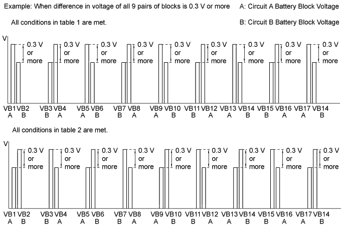
Compare the battery block voltages (Battery block Vol -V01 to V17) between the even and odd number groups in each combination shown in the table below.
Table 1 Circuit A Battery Block Circuit B Battery Block Condition Battery Block Vol-V01 (VB1) Battery Block Vol-V02 (VB2) "Battery Block Vol - V01" - "Battery Block Vol - V02" = 0.3 V or more Battery Block Vol-V04 (VB4) Battery Block Vol-V03 (VB3) "Battery Block Vol - V04" - "Battery Block Vol - V03" = 0.3 V or more Battery Block Vol-V05 (VB5) Battery Block Vol-V06 (VB6) "Battery Block Vol - V05" - "Battery Block Vol - V06" = 0.3 V or more Battery Block Vol-V08 (VB8) Battery Block Vol-V07 (VB7) "Battery Block Vol - V08" - "Battery Block Vol - V07" = 0.3 V or more Battery Block Vol-V09 (VB9) Battery Block Vol-V10 (VB10) "Battery Block Vol - V09" - "Battery Block Vol - V10" = 0.3 V or more Battery Block Vol-V12 (VB12) Battery Block Vol-V11 (VB11) "Battery Block Vol - V12" - "Battery Block Vol - V11" = 0.3 V or more Battery Block Vol-V13 (VB13) Battery Block Vol-V14 (VB14) "Battery Block Vol - V13" - "Battery Block Vol - V14" = 0.3 V or more Battery Block Vol-V16 (VB16) Battery Block Vol-V15 (VB15) "Battery Block Vol - V16" - "Battery Block Vol - V15" = 0.3 V or more Battery Block Vol-V17 (VB17) Battery Block Vol-V14 (VB14) "Battery Block Vol - V17" - "Battery Block Vol - V14" = 0.3 V or more Table 2 Circuit A Battery Block Circuit B Battery Block Condition Battery Block Vol-V01 (VB1) Battery Block Vol-V02 (VB2) "Battery Block Vol - V02" - "Battery Block Vol - V01" = 0.3 V or more Battery Block Vol-V04 (VB4) Battery Block Vol-V03 (VB3) "Battery Block Vol - V03" - "Battery Block Vol - V04" = 0.3 V or more Battery Block Vol-V05 (VB5) Battery Block Vol-V06 (VB6) "Battery Block Vol - V06" - "Battery Block Vol - V05" = 0.3 V or more Battery Block Vol-V08 (VB8) Battery Block Vol-V07 (VB7) "Battery Block Vol - V07" - "Battery Block Vol - V08" = 0.3 V or more Battery Block Vol-V09 (VB9) Battery Block Vol-V10 (VB10) "Battery Block Vol - V10" - "Battery Block Vol - V09" = 0.3 V or more Battery Block Vol-V12 (VB12) Battery Block Vol-V11 (VB11) "Battery Block Vol - V11" - "Battery Block Vol - V12" = 0.3 V or more Battery Block Vol-V13 (VB13) Battery Block Vol-V14 (VB14) "Battery Block Vol - V14" - "Battery Block Vol - V13" = 0.3 V or more Battery Block Vol-V16 (VB16) Battery Block Vol-V15 (VB15) "Battery Block Vol - V15" - "Battery Block Vol - V16" = 0.3 V or more Battery Block Vol-V17 (VB17) Battery Block Vol-V14 (VB14) "Battery Block Vol - V14" - "Battery Block Vol - V17" = 0.3 V or more Tech Tips
Make sure to compare Battery Block Vol-V17 to Battery Block Vol-V14 in accordance with the table above.
Tech Tips
When an internal malfunction occurs in the battery smart unit, this symptom (difference in voltage of 0.3 V or more for all 9 pairs of blocks) will occur.
Result Result Proceed to All conditions in table 1 are met. A All conditions in table 2 are met. Other than above. B -
Turn the power switch off.
-
Disconnect the Techstream from the DLC3.
B
REPLACE HV BATTERY Click here
A 
REPLACE BATTERY SMART UNIT Click here
-