HYBRID CONTROL SYSTEM, Diagnostic DTC:U0100-530, U0129-527, U0129-528, U0140-146, U0151-763, U0164-827, U1107-436

| DTC Code | DTC Name |
|---|---|
| U0100-530 | Lost Communication with ECM / PCM "A" |
| U0129-527 | Lost Communication with Brake System Control Module |
| U0129-528 | Lost Communication with Brake System Control Module |
| U0140-146 | Communication Error from Body ECU to HV ECU |
| U0151-763 | Communication Error from Airbag ECU to HV ECU |
| U0164-827 | Communication Error from A/C ECU to HV ECU |
| U1107-436 | Lost Communication with Power Management Module |
DESCRIPTION
The power management control ECU transmits and receives signals via CAN communication to and from the ECM, skid control ECU assembly, power steering ECU assembly, main body ECU, airbag sensor assembly, and air conditioning amplifier assembly.
| DTC No. | INF Code | DTC Detection Condition | Trouble Area |
|---|---|---|---|
| U0100 | 530 | Problem with CAN communication between the ECM and power management control ECU (CAN communication system malfunction) (1 trip detection logic) |
CAN communication system |
| U0129 | 527 | Problem with CAN communication (V BUS) between the skid control ECU assembly and power management control ECU (CAN communication system malfunction) (1 trip detection logic) |
|
| 528 | Problem with CAN communication between the skid control ECU assembly and power management control ECU (CAN communication system malfunction) (1 trip detection logic) |
||
| U0140 | 146 | Problem with CAN communication between the main body ECU and power management control ECU (CAN communication system malfunction) (1 trip detection logic) |
|
| U0151 | 763 | Problem with CAN communication between airbag sensor assembly and power management control ECU (CAN communication system malfunction) (1 trip detection logic) |
|
| U0164 | 827 | Problem with CAN communication between air conditioning amplifier assembly and power management control ECU (CAN communication system malfunction) (1 trip detection logic) |
|
| U1107 | 436 | Problem with CAN communication between the power source ECU and power management control ECU (CAN communication system malfunction) (1 trip detection logic) |
MONITOR DESCRIPTION
If the power management control ECU detects a problem with CAN communication with the ECU, it will illuminate the MIL and store a DTC.
MONITOR STRATEGY
| Related DTCs | U0100 (INF 211/212/530): Verify communication |
| Required sensors / components | Main: Power management control ECU Sub: CAN bus line |
| Frequency of operation | Continuous |
| Duration | TMC's intellectual property |
| MIL operation | Immediately |
| Sequence of operation | None |
TYPICAL ENABLING CONDITIONS
| The monitor will run whenever the following DTCs are not present | TMC's intellectual property |
| Other conditions belong to TMC's intellectual property | - |
TYPICAL MALFUNCTION THRESHOLDS
| TMC's intellectual property | - |
COMPONENT OPERATING RANGE
| Power management control ECU | DTC U0100 (INF 211/212/530) is not detected |
CONFIRMATION DRIVING PATTERN
-
Connect the Techstream to the DLC3.
-
Turn the power switch on (IG) and turn the Techstream on.
-
Clear the DTCs (even if no DTCs are stored, perform the clear DTC procedure).
-
Turn the power switch off and wait for 30 seconds or more.
-
Turn the power switch on (IG) and turn the Techstream on.
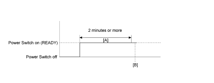
-
Turn the power switch on (READY) and wait for 2 minutes or more. [A]
-
Enter the following menus: Powertrain / Hybrid Control / Trouble Codes. [B]
-
Read the current DTCs.
Tech Tips
-
If a current DTC is output, the system is malfunctioning.
-
If current DTCs are not output, perform the following steps to check for permanent DTCs.
-
-
Check that the permanent DTCs are cleared.
-
If the permanent DTCs are not cleared, perform a universal trip, and then check for permanent DTCs again.
INSPECTION PROCEDURE
Tech Tips
After the repair, clear the DTCs and perform the following procedure to check that DTCs are not output.
-
Turn the power switch on (IG) and wait for 2 minutes or more.
PROCEDURE
-
CHECK DTC OUTPUT (ALL)
-
Connect the Techstream to the DLC3.
-
Turn the power switch on (IG).
-
Check for DTCs of all systems by following the prompts on the Techstream screen.
-
Check if DTCs are output.
Result Result Proceed to Power management control ECU outputs P2532-772 A Power management control ECU does not output P2532-772 B -
Turn the power switch off.
B 
GO TO CAN COMMUNICATION SYSTEM Click here
A 
GO TO DTC CHART (P2532-772) Click here
-