HYBRID CONTROL SYSTEM, Diagnostic DTC:P0A94-587

| DTC Code | DTC Name |
|---|---|
| P0A94-587 | DC / DC Converter Performance |
DTC SUMMARY
MALFUNCTION DESCRIPTIONThe power management control ECU detects a VB sensor or VL sensor malfunction.
The cause of this malfunction may be one of the following:
-
A VH sensor, VL sensor or VB sensor circuit malfunction
-
Voltage sensor malfunction
-
Motor generator control ECU malfunction
-
Communication (wire harness) malfunction
-
High voltage system malfunction
-
HV battery malfunction
-
Hybrid battery junction block assembly malfunction
-
Inverter with converter assembly malfunction
-
High-voltage wire harness malfunction
-
High-voltage connector or connection malfunction
| Inspection Content | Reason (Narrow Down in Order Using Inspection Procedures Below) | Inspection Step |
|---|---|---|
| Check for DTCs (HV) | Output DTCs | 1 |
| Check for DTCs (check voltage sensor malfunction locations) Check for DTCs (drive test) |
Put vehicle in ready ON (vehicle stopped or being driven) and then check whether DTCs are output again. | 3, 4 |
| Read value using GTS | Data List value | 5 |
| Check freeze frame data (HV) | FREEZE FRAME DATA | 6, 7 |
| Read value using GTS | Accelerator and brake pedal simultaneously depressed Data List value | 8 |
DESCRIPTION
For a description of the boost converter Click here.
The MG ECU uses a voltage sensor (VL) that is built into the boost converter to detect the high voltage before it is boosted. The ECU also uses the battery smart unit to detect HV battery voltage (VB).
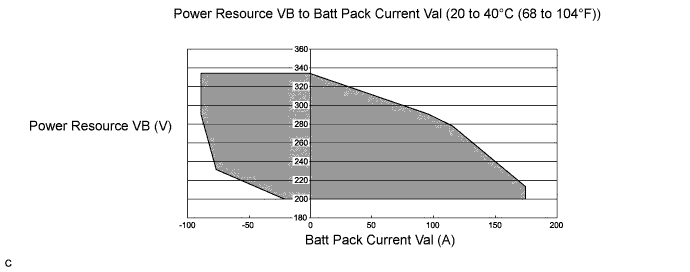
Tech Tips
Using the Techstream, check the Data List of "Power Resource VB" and "Batt Pack Current Val". If these values are not within the below range, there is a battery smart unit malfunction.
| DTC No. | INF Code | DTC Detection Condition | Trouble Area |
|---|---|---|---|
| P0A94 | 587 | Voltages from HV battery voltage (VB) sensor and boost converter voltage (VL) sensor deviate: Difference between "VL-Voltage before Boosting" and "Power Resource VB" is large when the boosting request is given. (1 trip detection logic) |
|
| Related Data List | ||||
|---|---|---|---|---|
|
MONITOR DESCRIPTION
The power management control ECU monitors signals of HV battery voltage (VB) and boost converter voltage (VL) sensors. When a large difference occurs between the voltages from the VB and VL sensors, the power management control ECU interprets this as a failure of either of the sensors. The power management control ECU will illuminate the MIL and store a DTC.
MONITOR STRATEGY
| Related DTCs | P0A94 (INF 587): Voltage (VB or VL) sensor deviation |
| Required sensors / components | Boost converter |
| Frequency of operation | Continuous |
| Duration | TMC's intellectual property |
| MIL operation | 1 driving cycle |
| Sequence of operation | None |
TYPICAL ENABLING CONDITIONS
| The monitor will run whenever the following DTCs are not present | TMC's intellectual property |
| Other conditions belong to TMC's intellectual property | - |
TYPICAL MALFUNCTION THRESHOLDS
| TMC's intellectual property | - |
COMPONENT OPERATING RANGE
| Power management control ECU | DTC P0A94 (INF 587) is not detected |
CONFIRMATION DRIVING PATTERN
-
Connect the Techstream to the DLC3.
-
Turn the power switch on (IG) and turn the Techstream on.
-
Clear the DTCs (even if no DTCs are stored, perform the clear DTC procedure).
-
Turn the power switch off and wait for 30 seconds or more.
-
Turn the power switch on (IG) and turn the Techstream on.
-
Turn the power switch on (READY).
-
With the shift lever in D, depress both the accelerator pedal and brake pedal at the same time to raise the SOC to a sufficient level.
-
Move the shift lever to P, check that the engine is stopped and move the shift lever to N.
-
Set the A/C for maximum cooling.
-
Leave the vehicle for a few minutes.
-
Enter the following menus: Powertrain / Hybrid Control / Trouble Codes.
-
Read the current DTCs.
Tech Tips
-
If a current DTC is output, the system is malfunctioning.
-
If current DTCs are not output, perform the following steps to check for permanent DTCs.
-
-
Check that the permanent DTCs are cleared.
-
If the permanent DTCs are not cleared, perform the universal trip, and then check for permanent DTCs again.
INSPECTION PROCEDURE
Tech Tips
When the accelerator pedal is not depressed with the power switch on (READY) and the shift lever in P, if "VL-Voltage before Boosting" and the "Power Resource VB" is approximately same after repair, the condition is judged as normal.
PROCEDURE
-
CHECK DTC OUTPUT (HYBRID CONTROL)
-
Connect the Techstream to the DLC3.
-
Turn the power switch on (IG).
-
Enter the following menus: Powertrain / Hybrid Control / Trouble Codes.
-
Check if DTCs are output.
Result Result Proceed to One of the following applies:
-
Only P0A94-587 is output.
-
DTCs other than "P0A94-442 and DTCs in Chart Below" are output at the same time.
A P0A94-587 and P0A94-442 (voltage execution value malfunction) are output at the same time. B DTC indicated in Table 1 is output at the same time. C DTC indicated in Table 2 is output at the same time. D Table 1 Malfunction Content Relevant DTC Microcomputer malfunction P0A1A-151, 155, 156, 658, 659 Generator Control Module P0A1B-164, 193, 512, 661, 786 Drive Motor "A" Control Module P0A1D-148 Hybrid Powertrain Control Module P324E-788 MG-ECU Power Relay Intermittent Circuit Power source circuit malfunction P2511-149 HV CPU Power Relay Sense Circuit Intermittent No Continuity Communication system malfunction U0110 (all INF codes)*1 Lost Communication with Drive Motor Control Module "A" Sensor and actuator circuit malfunction P0A78-266, 267 Drive Motor "A" Inverter Performance P0A94-585 DC / DC Converter Performance P0A94-589, 590 DC / DC Converter Performance P0AFC-129 Hybrid Battery Pack Sensor Module System malfunction P3004-132 High Voltage Power Resource Table 2 Malfunction Content Relevant DTC Microcomputer malfunction P0AFC-123 Hybrid Battery Pack Sensor Module Sensor and actuator circuit malfunction P0B3D-123 Hybrid Battery Voltage Sensor "A" Circuit Low P0B42-123 Hybrid Battery Voltage Sensor "B" Circuit Low P0B47-123 Hybrid Battery Voltage Sensor "C" Circuit Low P0B4C-123 Hybrid Battery Voltage Sensor "D" Circuit Low P0B51-123 Hybrid Battery Voltage Sensor "E" Circuit Low P0B56-123 Hybrid Battery Voltage Sensor "F" Circuit Low P0B5B-123 Hybrid Battery Voltage Sensor "G" Circuit Low P0B60-123 Hybrid Battery Voltage Sensor "H" Circuit Low P0B65-123 Hybrid Battery Voltage Sensor "I" Circuit Low P0B6A-123 Hybrid Battery Voltage Sensor "J" Circuit Low P0B6F-123 Hybrid Battery Voltage Sensor "K" Circuit Low P0B74-123 Hybrid Battery Voltage Sensor "L" Circuit Low P0B79-123 Hybrid Battery Voltage Sensor "M" Circuit Low P0B7E-123 Hybrid Battery Voltage Sensor "N" Circuit Low P0B83-123 Hybrid Battery Voltage Sensor "O" Circuit Low P0B88-123 Hybrid Battery Voltage Sensor "P" Circuit Low P0B8D-123 Hybrid Battery Voltage Sensor "Q" Circuit Low P0B92-123 Hybrid Battery Voltage Sensor "R" Circuit Low P308A-123 Hybrid Battery Voltage Sensor ALL Circuit Low Tech Tips
-
*1: If any INF codes are output for this DTC, refer to the corresponding diagnostic procedure.
-
P0A94-587 may be output at the same time as a result of the malfunction indicated by the DTCs above.
-
The chart above is listed in inspection order of priority.
-
Check DTCs that are output at the same time by following the listed order. (The main cause of the malfunction can be determined without performing unnecessary inspections.)
-
-
Turn the power switch off.
B 
REPLACE INVERTER WITH CONVERTER ASSEMBLY Click here
C
GO TO DTC CHART (HYBRID CONTROL SYSTEM) Click here
D
GO TO DTC CHART (HYBRID BATTERY SYSTEM) Click here
A 
-
-
CLEAR DTC
-
Connect the Techstream to the DLC3.
-
Turn the power switch on (IG).
-
Enter the following menus: Powertrain / Hybrid Control / Trouble Codes.
-
Clear DTCs and freeze frame data.
-
Turn the power switch off.
NEXT
-
-
CHECK DTC OUTPUT (CHECK FAILURE PART)
-
Apply the parking brake and secure the wheels using chocks.
-
Connect the Techstream to the DLC3. (*1)
-
Turn the power switch on (READY). (*2)
-
Enter the following menus: Powertrain / Hybrid Control / Data List (*3)
-
If both "Power Resource VB" and "VL-Voltage before Boosting" are less than 280 V, move the shift lever to D and depress both the accelerator pedal and brake pedal at the same time to raise them to 280 V or more. (*4)
-
Move the shift lever to P. (*5)
-
Set the air conditioning to MAX COOL and turn the headlights on. (*6)
-
Confirm that "Batt Pack Current Val" is more than 3 A. (*7)
-
With the engine stopped and the conditions of steps *5, *6 and *7 satisfied, leave the vehicle for 15 seconds. *8
-
Enter the following menus: Powertrain / Hybrid Control / DTC. (*9)
-
Check if DTCs. (*10)
Note
If the low HV battery information comes on, Move the shift lever to P and start the engine to charge the HV battery. After the engine stops, perform steps (*1) through (*10) again.
Result Result Proceed to No DTCs are output, or DTCs except the following are output. A P0AFC-129 (HV battery voltage circuit malfunction) is output. B P0A94-585 (boost converter voltage (VL) sensor performance problem) is output. C P3000-388 (discharge inhibition) is output. D P3004-132 (high voltage power supply line problem) is output. E -
Turn the power switch off.
B
REPLACE BATTERY SMART UNIT Click here
C
REPLACE INVERTER WITH CONVERTER ASSEMBLY Click here
D
LEAVE VEHICLE WITH SHIFT LEVER IN P, AND CHARGE HV BATTERY BY IDLING UNTIL IDLING STOPS (PERFORM STEPS (*1) THROUGH (*10))
E
REPLACE BATTERY SMART UNIT Click here
A
-
-
CHECK DTC OUTPUT (ROAD TEST)
-
Turn the power switch on (READY). (*11)
-
Perform a road test that repeats full acceleration to 60 km/h (37 mph) and then braking to a complete stop three times. (*12)
-
Connect the Techstream to the DLC3. (*13)
-
Enter the following menus: Powertrain / Hybrid Control / Trouble Codes. (*14)
-
Check if DTCs. (*15)
Result Result Proceed to No DTCs are output, or DTCs except the following are output. A P0AFC-129 (HV battery voltage circuit malfunction) is output. B P0A94-585 (boost converter voltage (VL) sensor performance problem) is output. C P3000-388 (discharge inhibition) is output. D P3004-132 (high voltage power supply line problem) is output. E -
Turn the power switch off.
B
REPLACE BATTERY SMART UNIT Click here
C
REPLACE INVERTER WITH CONVERTER ASSEMBLY Click here
D
LEAVE VEHICLE WITH SHIFT LEVER IN P, AND CHARGE HV BATTERY BY IDLING UNTIL IDLING STOPS (PERFORM STEPS (*11) THROUGH (*15))
E
REPLACE BATTERY SMART UNIT Click here
A
-
-
READ VALUE USING TECHSTREAM
-
Apply the parking brake and secure the wheels using chocks.
-
Connect the Techstream to the DLC3.
-
Turn the power switch on (READY).
-
Enter the following menus: Powertrain / Hybrid Control / Data List / Power Resource VB, VL-Voltage before Boosting, VH-Voltage after Boosting.
-
If both "Power Resource VB" and VL-Voltage before Boosting are less than 280 V, move the shift lever to D and depress both the accelerator pedal and brake pedal at the same time to raise them to 280 V or more.
-
Turn the engine off, move the shift lever to P, and read the Data List when the vehicle is stationary.
Result Result Proceed to Both of the following are not satisfied. A Both of the following are satisfied:
-
Difference between "Power Resource VB" and "VH-Voltage after Boosting" is less than 5 V.
-
Difference between "VL-Voltage before Boosting" and "VH-Voltage after Boosting" is more than 30 V.
B Both of the following are satisfied:
-
Difference between "VH-Voltage after Boosting" and "VL-Voltage before Boosting" is less than 5 V.
-
Difference between "Power Resource VB" and "VH-Voltage after Boosting" is more than 15 V.
C -
-
Turn the power switch off.
B
REPLACE INVERTER WITH CONVERTER ASSEMBLY Click here
C
REPLACE BATTERY SMART UNIT Click here
A
-
-
CHECK FREEZE FRAME DATA (HYBRID CONTROL)
-
Connect the Techstream to the DLC3.
-
Turn the power switch on (IG).
-
Enter the following menus: Powertrain / Hybrid Control / Trouble Codes.
-
Read the freeze frame data of DTC P0A94-587.
Result Result Proceed to Both of the following are satisfied or both of the following are not satisfied. A "Power Resource VB" is less than 190 V or more than 340 V. B "VL-Voltage before Boosting" is less than 190 V or more than 340 V. C -
Turn the power switch off.
B
REPLACE BATTERY SMART UNIT Click here
C
REPLACE INVERTER WITH CONVERTER ASSEMBLY Click here
A
-
-
CHECK FREEZE FRAME DATA (HYBRID CONTROL)
-
Connect the Techstream to the DLC3.
-
Turn the power switch on (IG).
-
Enter the following menus: Powertrain / Hybrid Control / Trouble Codes.
-
Read the freeze frame data of DTC P0A94-587.
Tech Tips
In the freeze frame data, read the "Power Resource VB" and all of the "Battery Block Vol".
Result Result Proceed to Freeze frame data is not stored. A Both of the following are satisfied:
-
Sum of all "Battery Block Vol" is more than ("Power Resource VB" - 45 V)
-
Sum of all "Battery Block Vol" is less than ("Power Resource VB" + 30 V)
B Neither A nor B is satisfied. C -
-
Turn the power switch off.
B
REPLACE INVERTER WITH CONVERTER ASSEMBLY Click here
C
REPLACE BATTERY SMART UNIT Click here
A
-
-
READ VALUE USING TECHSTREAM
-
Apply the parking brake and secure the wheels using chocks.
-
Connect the Techstream to the DLC3.
-
Turn the power switch on (READY).
-
Enter the following menus: Powertrain / Hybrid Control / Data List.
-
If both "Battery Block Vol" and "VL-Voltage before Boosting" are less than 280 V, move the shift lever to D and depress both the accelerator pedal and brake pedal at the same time to raise them to 280 V or more.
-
Turn the engine off, move the shift lever to P, and read the "Power Resource VB" and all of the "Battery Block Vol", when the vehicle is stationary.
Result Result Proceed to Both of the following are satisfied:
-
Sum of all "Battery Block Vol" is more than ("Power Resource VB" -45 V)
-
Sum of all "Battery Block Vol" is less than ("Power Resource VB" +30 V)
A The preceding condition is not satisfied. B -
-
Turn the power switch off.
B
REPLACE BATTERY SMART UNIT Click here
A 
REPLACE INVERTER WITH CONVERTER ASSEMBLY Click here
-