HYBRID CONTROL SYSTEM, Diagnostic DTC:P0A93-346

| DTC Code | DTC Name |
|---|---|
| P0A93-346 | Inverter Cooling System Performance |
DTC SUMMARY
MALFUNCTION DESCRIPTIONThis indicates when the temperature inside the inverter has become abnormal. The cause of this malfunction may be one of the following:
-
Hybrid cooling system malfunction
-
Coolant is leaking, insufficient, coolant level, frozen or the passenger of coolant is clogged.
-
Grille is blocked.
-
Internal inverter malfunction
-
Inverter internal circuit malfunction
-
Malfunction in ECU that controls the inverter
-
Malfunction in sensor for inverter control (coolant sensor)
DESCRIPTION
Refer to the system description for the cooling system Click here.
| DTC No. | INF Code | DTC Detection Condition | Trouble Area |
|---|---|---|---|
| P0A93 | 346 | Inverter coolant temperature increases as well as the temperature of any inverter with converter assembly related parts due to an inverter cooling system malfunction. (1 trip detection logic) |
|
| DTC No. | ECU Data List |
|---|---|
| P0A93-346 |
|
MONITOR DESCRIPTION
If the power management control ECU detects a malfunction of the inverter water pump assembly, fan or radiator, the ECU will illuminate the MIL and set a DTC.
MONITOR STRATEGY
| Related DTCs | P0A93 (INF 346): HV cooling system malfunction |
| Required sensors / components | Inverter water pump assembly |
| Frequency of operation | Continuous |
| Duration | TMC's intellectual property |
| MIL operation | 1 driving cycle |
| Sequence of operation | None |
TYPICAL ENABLING CONDITIONS
| The monitor will run whenever the following DTCs are not present | TMC's intellectual property |
| Other conditions belong to TMC's intellectual property | - |
TYPICAL MALFUNCTION THRESHOLDS
| TMC's intellectual property | - |
COMPONENT OPERATING RANGE
| Power management control ECU | DTC P0A93 (INF 346) is not detected |
CONFIRMATION DRIVING PATTERN
-
Connect the Techstream to the DLC3.
-
Turn the power switch on (IG) and turn the Techstream on.
-
Clear the DTCs (even if no DTCs are stored, perform the clear DTC procedure).
-
Turn the power switch off and wait for 30 seconds or more.
-
Turn the power switch on (IG) and turn the Techstream on.
-
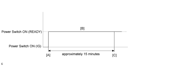
Turn the power switch on (READY). [A]
-
Perform a road test according to the freeze frame data item "Vehicle Spd" for approximately 15 minutes. [B]
During the road test, check Data List items "Inverter Coolant Water Temperature", "Inverter Temp- (MG2)", "Inverter Temp- (MG1)", "DC/DC Cnv Temp (Upper)", " DC/DC Cnv Temp (Lower)" and "Engine Coolant Temp" to prevent them from overheating.
-
Enter the following menus: Powertrain / Hybrid Control / Trouble Codes. [C]
-
Read the current DTCs.
Tech Tips
-
If a current DTC is output, the system is malfunctioning.
-
If current DTCs are not output, perform the following steps to check for permanent DTCs.
-
-
Check that the permanent DTCs are cleared.
-
If the permanent DTCs are not cleared, perform a universal trip, and then check for permanent DTCs again.
INSPECTION PROCEDURE
CAUTION:
-
Before inspecting the high-voltage system or disconnecting the low voltage connector of the inverter with converter assembly, take safety precautions such as wearing insulated gloves and removing the service plug grip to prevent electrical shocks. After removing the service plug grip, put it in your pocket to prevent other technicians from accidentally reconnecting it while you are working on the high-voltage system.
-
After removing the service plug grip, wait for at least 10 minutes before touching any of the high-voltage connectors or terminals. After waiting for 10 minutes, check the voltage at the terminals in the inspection point in the inverter with converter assembly. The voltage should be 0 V before beginning work Click here.
Tech Tips
Waiting for at least 10 minutes is required to discharge the high-voltage capacitor inside the inverter with converter assembly.
Note
-
After turning the power switch off, waiting time may be required before disconnecting the cable from the negative (-) auxiliary battery terminal. Therefore, make sure to read the disconnecting the cable from the negative (-) auxiliary battery terminal notices before proceeding with work Click here.
-
If DTC P0A78-284, 286, P0A7A-322, 324, P0A94-553 or 557 is output, replace the inverter with converter assembly after this inspection.
Tech Tips
After the repair, clear the DTCs and perform the following procedure to check that DTCs are not output.
-
Perform a road test according to the freeze frame data item "Vehicle Spd" for approximately 15 minutes.
During the road test, check Data List items "Inverter Coolant Water Temperature", "Inverter Temp-(MG2)", "Inverter Temp- (MG1)", "DC/DC Cnv Temp (Upper)" and " DC/DC Cnv Temp (Lower)" to prevent them from overheating.
PROCEDURE
-
CHECK DTC OUTPUT (HYBRID CONTROL)
-
Connect the Techstream to the DLC3.
-
Turn the power switch on (IG).
-
Enter the following menus: Powertrain / Hybrid Control / Trouble Codes.
-
Check if DTCs are output.
Result Result Proceed to P0A93-346 only is output, or DTCs except the ones in the table below are also output. A Any of the following DTCs are also output. B DTC No. Relevant Diagnosis P0A02-719 Motor Electronics Coolant Temperature Sensor Circuit Low P0A03-720 Motor Electronics Coolant Temperature Sensor Circuit High P0C73-776 Motor Electronics Coolant Pump "A" Control Performance P314A-828 Inverter Coolant Pump Speed Signal Tech Tips
-
P0A93-346 may be output as a result of the malfunction indicated by the DTCs above.
-
-
Turn the power switch off.
B 
GO TO DTC CHART (HYBRID CONTROL SYSTEM) Click here
A 
-
-
CHECK CONNECTOR CONNECTION CONDITION (INVERTER WITH CONVERTER ASSEMBLY CONNECTOR)
CAUTION:
Be sure to wear insulated gloves.
-
Check that the service plug grip is not installed.
Note
After removing the service plug grip, do not turn the power switch on (READY), unless instructed by the repair manual because this may cause a malfunction.
-
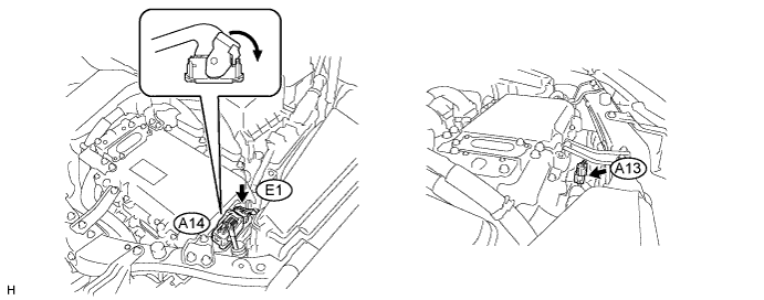
Check the connection condition of the low voltage connector of the inverter with converter assembly and the contact pressure of each terminal. Check the terminals for deformation, and check the connector for water ingress and foreign matter Click here.
Note
Before disconnecting the connector, confirm that it is properly connected by checking that the locking claws are engaged and that the connector does not pull out.
OK - The connector is connected securely. - The terminals are not deformed and are connected securely. - No water or foreign matter in the connector. Result Result Proceed to OK A NG (The connector is not connected securely.) B NG (The terminals are not making secure contact or are deformed, or water or foreign matter exists in the connector.) C Tech Tips
When connecting the connector, insert it with the locking lever in the raised position. Rotate the lever downward and make sure that the connector is pulled into its socket. When the locking lever is in its fully closed position, a click will be heard as its locking claws engage. After the click is heard, pull up on the connector to confirm that it is properly connected.
B
CONNECT SECURELY
C
REPAIR OR REPLACE HARNESS OR CONNECTOR
A
-
-
CHECK COOLING SYSTEM
Tech Tips
If the "Cooling System" inspection results are normal, perform the next step.
NEXT 
REPLACE INVERTER WATER PUMP ASSEMBLY Click here