HYBRID CONTROL SYSTEM, Diagnostic DTC:P0C3A-621, P0C3B-622, P0C3F-623, P0C40-624

| DTC Code | DTC Name |
|---|---|
| P0C3A-621 | DC / DC Converter Temperature Sensor "A" Low |
| P0C3B-622 | DC / DC Converter Temperature Sensor "A" High |
| P0C3F-623 | DC / DC Converter Temperature Sensor "B" Low |
| P0C40-624 | DC / DC Converter Temperature Sensor "B" High |
DESCRIPTION
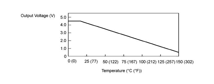
The MG ECU, which is built into in the inverter with converter assembly, detects the boost converter temperature using the temperature sensor in the boost converter. The boost converter temperature sensor outputs voltage that changes between 0.5 and 4.5 V according to changes in temperature. The higher the boost converter temperature is, the lower the output voltage will be. Conversely, the lower the boost converter temperature is, the higher the output voltage will be. The MG ECU controls load based on signals sent from the boost converter temperature sensor to prevent overheating. The MG ECU detects malfunctions in the boost converter temperature sensor and its wiring.
| DTC No. | INF Code | DTC Detection Condition | Trouble Area |
|---|---|---|---|
| P0C3A | 621 | Open or short to ground in the boost converter temperature sensor (upper) signal circuit (1 trip detection logic) |
Inverter with converter assembly |
| P0C3B | 622 | Short to +B in the boost converter temperature sensor (upper) signal circuit (1 trip detection logic) |
|
| P0C3F | 623 | Open or short to ground in the boost converter temperature sensor (lower) signal circuit (1 trip detection logic) |
|
| P0C40 | 624 | Short to +B in the boost converter temperature sensor (lower) signal circuit (1 trip detection logic) |
| DTC No. | Data List |
|---|---|
| P0C3A-621 | DC/DC Cnv Temp (Upper) |
| P0C3B-622 | |
| P0C3F-623 | DC/DC Cnv Temp (Lower) |
| P0C40-624 |
INSPECTION PROCEDURE
Tech Tips
After the repair, clear the DTCs and perform the following procedure to check that DTCs are not output.
-
Turn the power switch on (IG) and wait for 5 seconds or more.
