HYBRID CONTROL SYSTEM, Diagnostic DTC:P0A78-266, P0A78-267

| DTC Code | DTC Name |
|---|---|
| P0A78-266 | Drive Motor "A" Inverter Performance |
| P0A78-267 | Drive Motor "A" Inverter Performance |
DESCRIPTION
The inverter contains a three-phase bridge circuit, which consists of six power transistors (IGBTs) each for generator (MG1) and motor (MG2). The inverter converts high-voltage direct current from the HV battery into three-phase alternating current for generator (MG1) and motor (MG2); it also converts three-phase alternating current supplied by generator (MG1) and motor (MG2) into direct current for the HV battery. The MG ECU controls the actuation of the power transistors (IGBTs). The inverter transmits information necessary for control, such as amperage and voltage, to the MG ECU.
Tech Tips
The term "drive motor A" indicates motor (MG2).
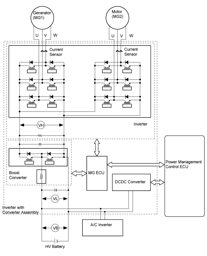
The MG ECU uses an inverter voltage sensor, which is built into the inverter, to detect boosted high voltage to allow control of the voltage boost.
The inverter voltage sensor outputs voltage that fluctuates between 0 to 5 V according to changes in VH.
The MG ECU monitors the inverter voltage sensor and detects the following malfunctions.
| DTC No. | INF Code | DTC Detection Condition | Trouble Area |
|---|---|---|---|
| P0A78 | 266 | Drive motor "A" inverter voltage (VH) signal is stuck low: DTC stored when the VH sensor signal is excessively low. (1 trip detection logic) |
Inverter with converter assembly |
| 267 | Drive motor "A" inverter voltage (VH) signal is stuck high: DTC stored when the VH sensor signal is excessively high. (1 trip detection logic) |
| DTC No. | Data List |
|---|---|
| P0A78-266 | VH-Voltage after Boosting |
| P0A78-267 |
MONITOR DESCRIPTION
The MG ECU monitors the inverter voltage (VH) sensor circuit. If the MG ECU detects an open or short in the VH sensor circuit, the power management control ECU will illuminate the MIL and set a DTC.
MONITOR STRATEGY
| Related DTCs | P0A78 (INF 266): VH malfunction (GND short malfunction) P0A78 (INF 267): VH malfunction (+B short and disconnection malfunction) |
| Required sensors / components | Motor inverter |
| Frequency of operation | Continuous |
| Duration | TMC's intellectual property |
| MIL operation | 1 driving cycle |
| Sequence of operation | None |
TYPICAL ENABLING CONDITIONS
| The monitor will run whenever the following DTCs are not present | TMC's intellectual property |
| Other conditions belong to TMC's intellectual property | - |
TYPICAL MALFUNCTION THRESHOLDS
| TMC's intellectual property | - |
COMPONENT OPERATING RANGE
| Power management control ECU | DTC P0A78 (INF 266/267) is not detected |
CONFIRMATION DRIVING PATTERN
-
Connect the Techstream to the DLC3.
-
Turn the power switch on (IG) and turn the Techstream on.
-
Clear the DTCs (even if no DTCs are stored, perform the clear DTC procedure).
-
Turn the power switch off and wait for 30 seconds or more.
-
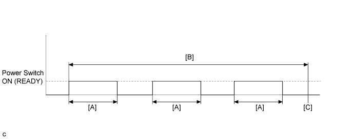
Turn the power switch on (READY) and after 5 seconds, turn the power switch off. [A]
-
Repeat [A] 3 times. [B]
-
Turn the power switch on (IG) and turn the Techstream on.
-
Enter the following menus: Powertrain / Hybrid Control / Trouble Codes. [C]
-
Read the current DTCs.
Tech Tips
-
If a current DTC is output, the system is malfunctioning.
-
If a current DTC is not output and want to confirm permanent DTC, perform the following procedure.
-
-
Check that permanent DTCs are cleared.
-
If the permanent DTCs are not cleared, perform the universal trip, and then check for permanent DTCs again.
INSPECTION PROCEDURE
Tech Tips
After the repair, clear the DTCs and perform the following procedure to check that DTCs are not output.
-
Turn the power switch on (READY) and wait for 5 seconds or more.
PROCEDURE
-
REPLACE INVERTER WITH CONVERTER ASSEMBLY
Tech Tips
The signal line from the drive motor "A" inverter voltage (VH) sensor is connected to the MG ECU inside the inverter with converter assembly. If P0A78-266 or P0A78-267 is output, replace the inverter with converter assembly.
NEXT 
COMPLETED