HYBRID CONTROL SYSTEM, Diagnostic DTC:P0705-757

| DTC Code | DTC Name |
|---|---|
| P0705-757 | Transmission Range Sensor Circuit |
DESCRIPTION
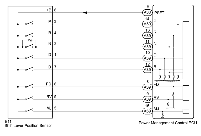
The shift lever position sensor can send 8 different switch signals to the power management control ECU. The power management control ECU uses the signals to detect the shift lever position (P, R, N, D, or B). The power management control ECU also uses this information to determine intended direction of travel (forward or reverse).
| DTC No. | INF Code | DTC Detection Condition | Trouble Area |
|---|---|---|---|
| P0705 | 757 | Shift sensor circuit malfunction (abnormal pattern) A malfunction in the P, R, N, D or B circuit is detected based on the shift sensor input pattern. (1 trip detection logic) |
|
| DTC No. | Data List |
|---|---|
| P0705-757 |
|
WIRING DIAGRAM
INSPECTION PROCEDURE
Tech Tips
After the repair, clear the DTCs and perform the following procedure to check that DTCs are not output.
-
Turn the power switch on (IG).
-
Slowly move the shift lever from P to D then back to P.
PROCEDURE
-
READ VALUE USING TECHSTREAM (SHIFT POSITION)
-
Connect the Techstream to the DLC3.
-
Turn the power switch on (IG).
-
Enter the following menus: Powertrain / Hybrid Control / Data List / Shift Sensor SW - P, Shift Sensor SW - R, Shift Sensor SW - N, Shift Sensor SW - D, Shift Sensor SW - B, Shift Sensor SW - FD, Shift Sensor SW - RV, Shift Sensor SW - MJ, .
-
While slowly moving the shift lever from P to B, then back to P, read the Data List (shift position) displayed on the Techstream.
Tech Tips
Be sure to move the shift lever slowly.
Result ECU Data List Shift Position P R N D B Shift Sensor SW-P ON OFF OFF OFF OFF Shift Sensor SW-R OFF ON OFF OFF OFF Shift Sensor SW-N OFF OFF ON OFF OFF Shift Sensor SW-D OFF OFF OFF ON OFF Shift Sensor SW-B OFF OFF OFF OFF ON Shift Sensor SW-FD OFF OFF OFF ON ON Shift Sensor SW-RV OFF ON OFF OFF OFF Shift Sensor SW-MJ ON ON ON ON ON -
Check if DTCs are output.
OK DTC P0705-757 is not output. -
Turn the power switch off.
NG 
CHECK SHIFT LEVER POSITION SENSOR Click here
OK 
-
-
CHECK FOR INTERMITTENT PROBLEMS
NG 
REPAIR OR REPLACE MALFUNCTIONING PARTS, COMPONENT AND AREA
OK 
REPLACE POWER MANAGEMENT CONTROL ECU Click here
-
CHECK SHIFT LEVER POSITION SENSOR
-
Turn the power switch on (IG).
-
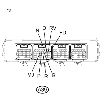
Text in Illustration *a Component with harness connected
(Power Management Control ECU)
Measure the voltage according to the value(s) in the table below.
Standard Voltage Tester Connection Condition Specified Condition A39-14 (P) - Body ground Power switch on (IG)
Shift lever in P
11 to 14 V A39-14 (P) - Body ground Power switch on (IG)
Any position except shift lever in P
0 to 1.5 V A39-13 (R) - Body ground Power switch on (IG)
Shift lever in R
11 to 14 V A39-13 (R) - Body ground Power switch on (IG)
Any position except shift lever in R
0 to 1.5 V A39-11 (N) - Body ground Power switch on (IG)
Shift lever in N
11 to 14 V A39-11 (N) - Body ground Power switch on (IG)
Any position except shift lever in N
1.2 to 2.8 V A39-10 (D) - Body ground Power switch on (IG)
Shift lever in D
11 to 14 V A39-10 (D) - Body ground Power switch on (IG)
Any position except shift lever in D
0 to 1.5 V A39-12 (B) - Body ground Power switch on (IG)
Shift lever in B
11 to 14 V A39-12 (B) - Body ground Power switch on (IG)
Any position except shift lever in B
0 to 1.5 V A39-15 (MJ) - Body ground Power switch on (IG)
Shift lever in P, R, N, D, or B
11 to 14 V A39-8 (FD) - Body ground Power switch on (IG)
Shift lever in D or B
11 to 14 V A39-8 (FD) - Body ground Power switch on (IG)
Any position except shift lever in D and B
0 to 1.5 V A39-9 (RV) - Body ground Power switch on (IG)
Shift lever in R
11 to 14 V A39-9 (RV) - Body ground Power switch on (IG)
Any position except shift lever in R
0 to 1.5 V -
Turn the power switch off.
NG
CHECK HARNESS AND CONNECTOR (POWER SOURCE CIRCUIT) Click here
OK
REPLACE POWER MANAGEMENT CONTROL ECU Click here
-
-
CHECK HARNESS AND CONNECTOR (POWER SOURCE CIRCUIT)
-
Disconnect the E11 shift lever position sensor connector.
-
Turn the power switch on (IG).
-
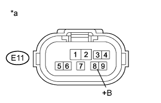
Text in Illustration *a Front view of wire harness connector
(to Shift Lever Position Sensor)
Measure the voltage according to the value(s) in the table below.
Standard Voltage Tester Connection Switch Condition Specified Condition E11-8 (+B) - Body ground Power switch on (IG) 11 to 14 V Note
Turning the power switch on (IG) with the shift lever position sensor connector disconnected causes other DTCs to be stored. Clear the DTCs after performing this inspection.
-
Turn the power switch off.
-
Reconnect the E11 shift lever position sensor connector.
NG
CHECK HARNESS AND CONNECTOR (SHIFT LEVER POSITION SENSOR - POWER MANAGEMENT CONTROL ECU) Click here
OK
-
-
INSPECT SHIFT LEVER POSITION SENSOR
-
Disconnect the E11 shift lever position sensor connector.
-
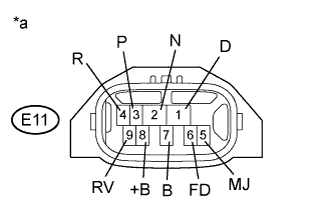
Text in Illustration *a Component without harness connected
(Shift Lever Position Sensor)
Measure the resistance according to the value(s) in the table below.
Standard Resistance (Check for Open) Tester Connection Condition Specified Condition E11-8 (+B) - E11-3 (P) Shift lever in P Below 1 Ω E11-8 (+B) - E11-5 (MJ) E11-8 (+B) - E11-4 (R) Shift lever in R Below 1 Ω E11-8 (+B) - E11-5 (MJ) E11-8 (+B) - E11-9 (RV) E11-8 (+B) - E11-2 (N) Shift lever in N Below 1 Ω E11-8 (+B) - E11-5 (MJ) E11-8 (+B) - E11-1 (D) Shift lever in D Below 1 Ω E11-8 (+B) - E11-6 (FD) E11-8 (+B) - E11-5 (MJ) E11-8 (+B) - E11-7 (B) Shift lever in B Below 1 Ω E11-8 (+B) - E11-6 (FD) E11-8 (+B) - E11-5 (MJ) Standard Resistance (Check for Short) Tester Connection Condition Specified Condition E11-8 (+B) or E11-3 (P) - Body ground and other terminals Shift lever in P 10 kΩ or higher*1 E11-8 (+B) or E11-5 (MJ) - Body ground and other terminals E11-8 (+B) or E11-4 (R) - Body ground and other terminals Shift lever in R 10 kΩ or higher*1 E11-8 (+B) or E11-5 (MJ) - Body ground and other terminals E11-8 (+B) or E11-9 (RV) - Body ground and other terminals E11-8 (+B) or E11-2 (N) - Body ground and other terminals Shift lever in N 10 kΩ or higher E11-8 (+B) or E11-5 (MJ) - Body ground and other terminals E11-8 (+B) or E11-1 (D) - Body ground and other terminals Shift lever in D 10 kΩ or higher*1 E11-8 (+B) or E11-6 (FD) - Body ground and other terminals E11-8 (+B) or E11-5 (MJ) - Body ground and other terminals E11-8 (+B) or E11-7 (B) - Body ground and other terminals Shift lever in B 10 kΩ or higher*1 E11-8 (+B) or E11-6 (FD) - Body ground and other terminals E11-8 (+B) or E11-5 (MJ) - Body ground and other terminals Note
*1: The resistance between terminals E11-8 (+B) and E11-2 (N) should be between 4.2 and 5.2 kΩ.
-
Reconnect the E11 shift lever position sensor connector.
NG
REPLACE SHIFT LEVER POSITION SENSOR Click here
OK
REPAIR OR REPLACE HARNESS OR CONNECTOR
-
-
CHECK HARNESS AND CONNECTOR (SHIFT LEVER POSITION SENSOR - POWER MANAGEMENT CONTROL ECU)
-
Disconnect the E11 shift lever position sensor connector.
-
Disconnect the A38 power management control ECU connector.
-
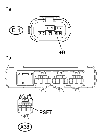
Text in Illustration *a Front view of wire harness connector
(to Shift Lever Position Sensor)
*b Rear view of wire harness connector
(to Power Management Control ECU)
Measure the resistance according to the value(s) in the table below.
Standard Resistance Tester Connection Switch Condition Specified Condition E11-8 (+B) - A38-9 (PSFT) Power switch off Below 1 Ω E11-8 (+B) or A38-9 (PSFT) - Body ground and other terminals Power switch off 10 kΩ or higher -
Reconnect the A38 power management control ECU connector.
-
Reconnect the E11 shift lever position sensor connector.
NG
REPAIR OR REPLACE HARNESS OR CONNECTOR
OK
REPAIR OR REPLACE POWER SOURCE CIRCUIT
-