HYBRID CONTROL SYSTEM, Diagnostic DTC:P0340-886

| DTC Code | DTC Name |
|---|---|
| P0340-886 | Camshaft Position Sensor "A" Circuit |
DESCRIPTION
The power management control ECU compares the engine speed sent from the ECM via CAN communication and the engine speed that is indicated by pulses sent from the ECM. If the pulse input is not normal, the power management control ECU sets this DTC.
| DTC No. | INF Code | DTC Detection Condition | Trouble Area |
|---|---|---|---|
| P0340 | 886 | Malfunction in the engine speed sensor (GI signal) circuit* (1 trip detection logic) |
|
Tech Tips
*: When this DTC is stored, vibration may occur when the engine is stopped.
| DTC No. | Data List |
|---|---|
| P0340-886 |
|
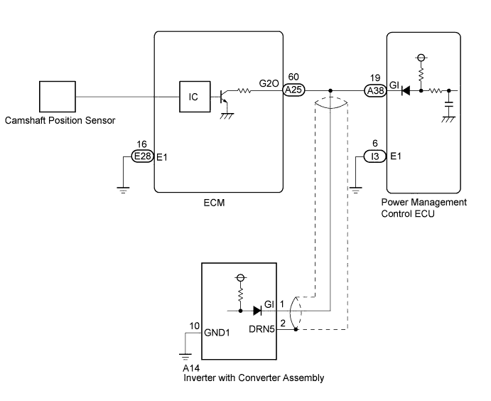
WIRING DIAGRAM
INSPECTION PROCEDURE
CAUTION:
-
Before inspecting the high-voltage system or disconnecting the low voltage connector of the inverter with converter assembly, take safety precautions such as wearing insulated gloves and removing the service plug grip to prevent electrical shocks. After removing the service plug grip, put it in your pocket to prevent other technicians from accidentally reconnecting it while you are working on the high-voltage system.
-
After removing the service plug grip, wait for at least 10 minutes before touching any of the high-voltage connectors or terminals. After waiting for 10 minutes, check the voltage at the terminals in the inspection point in the inverter with converter assembly. The voltage should be 0 V before beginning work Click here.
Tech Tips
Waiting for at least 10 minutes is required to discharge the high-voltage capacitor inside the inverter with converter assembly.
Note
After turning the power switch off, waiting time may be required before disconnecting the cable from the negative (-) auxiliary battery terminal. Therefore, make sure to read the disconnecting the cable from the negative (-) auxiliary battery terminal notices before proceeding with work Click here.
Tech Tips
After the repair, clear the DTCs and perform the following procedure to check that DTCs are not output.
-
Turn the power switch on (READY).
-
With the vehicle stopped, move the shift lever to P.
-
Depress the accelerator pedal to start the engine.
-
Depress the accelerator pedal and maintain the engine speed at 1000 rpm or more for 5 seconds or more.
PROCEDURE
-
CHECK DTC OUTPUT (HYBRID CONTROL)
-
Connect the Techstream to the DLC3.
-
Turn the power switch on (IG).
-
Enter the following menus: Powertrain / Hybrid Control / Trouble Codes.
-
Check if DTCs are output.
Result Result Proceed to P0340-886 only is output. A P0343-747 is also output. B -
Turn the power switch off.
B 
CHECK HARNESS AND CONNECTOR (ECM - POWER MANAGEMENT CONTROL ECU, INVERTER WITH CONVERTER) Click here
A 
-
-
CHECK CONNECTOR CONNECTION CONDITION (ECM CONNECTOR)
-
Check the connector connections and contact pressure of the relevant terminals for the ECM connectors Click here.
Note
Before disconnecting the connector, confirm that it is properly connected by checking that the locking claws are engaged and that the connector does not pull out.
OK The connectors are connected securely and there are no contact pressure problems. Tech Tips
When connecting the connector, insert it with the locking lever in the raised position. Rotate the lever downward and make sure that the connector is pulled into its socket. When the locking lever is in its fully closed position, a click will be heard as its locking claws engage. After the click is heard, pull up on the connector to confirm that it is properly connected.
NG 
CONNECT SECURELY
OK
-
-
CHECK CONNECTOR CONNECTION CONDITION (POWER MANAGEMENT CONTROL ECU CONNECTOR)
-
Check the connector connections and contact pressure of the relevant terminals for the power management control ECU connectors Click here.
OK The connectors are connected securely and there are no contact pressure problems.
NG
CONNECT SECURELY
OK
-
-
CHECK POWER MANAGEMENT CONTROL ECU (CHECK WAVEFORM)
-
Connect an oscilloscope between the power management control ECU terminals specified in the table below.
-
Turn the power switch on (READY).
-
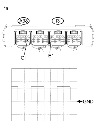
Text in Illustration *a Component with harness connected
(Power Management Control ECU)
Measure the waveform.
Item Content Terminal A38-19 (GI) - I3-6 (E1) Equipment Setting 5 V/DIV., 20 ms./DIV. Condition Power switch on (READY) with engine running Result Result Proceed to Normal A Waveform is flat, and is stuck on the +B side. B Waveform is flat, and is stuck on the GND side. C -
Turn the power switch off.
B
CHECK HARNESS AND CONNECTOR (POWER MANAGEMENT CONTROL ECU) Click here
C
CHECK HARNESS AND CONNECTOR (ECM - POWER MANAGEMENT CONTROL ECU, INVERTER WITH CONVERTER) Click here
A
-
-
CHECK FOR INTERMITTENT PROBLEMS
NG
REPAIR OR REPLACE MALFUNCTIONING PARTS, COMPONENT AND AREA
OK 
REPLACE POWER MANAGEMENT CONTROL ECU Click here
-
CHECK HARNESS AND CONNECTOR (POWER MANAGEMENT CONTROL ECU)
CAUTION:
Be sure to wear insulated gloves.
-
Check that the service plug grip is not installed.
Note
After removing the service plug grip, do not turn the power switch on (READY), unless instructed by the repair manual because this may cause a malfunction.
-
Disconnect the A25 ECM connector.
-
Disconnect the A14 inverter with converter assembly connector.
-
Connect the cable to the negative (-) auxiliary battery terminal.
-
Turn the power switch on (IG).
-
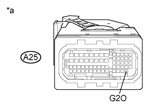
Text in Illustration *a Front view of wire harness connector
(to ECM)
Measure the voltage according to the value(s) in the table below.
Standard Voltage Tester Connection Switch Condition Specified Condition A25-60 (G2O) - Body ground Power switch on (IG) 11 to 14 V Note
Turning the power switch on (IG) with the ECM connector disconnected causes other DTCs to be stored. Clear the DTCs after performing this inspection.
-
Turn the power switch off.
-
Disconnect the cable from the negative (-) auxiliary battery terminal.
-
Reconnect the A14 inverter with converter assembly connector.
-
Reconnect the A25 ECM connector.
NG
REPAIR OR REPLACE HARNESS OR CONNECTOR
OK
REPLACE ECM Click here
-
-
CHECK HARNESS AND CONNECTOR (ECM - POWER MANAGEMENT CONTROL ECU, INVERTER WITH CONVERTER)
CAUTION:
Be sure to wear insulated gloves.
-
Check that the service plug grip is not installed.
Note
After removing the service plug grip, do not turn the power switch on (READY), unless instructed by the repair manual because this may cause a malfunction.
-
Disconnect the A25 ECM connector.
-
Disconnect the A38 power management control ECU connector.
-
Disconnect the A14 inverter with converter assembly connector.
-
Connect the cable to the negative (-) auxiliary battery terminal.
-
Turn the power switch on (IG).
-
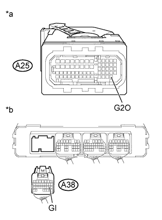
Text in Illustration *a Front view of wire harness connector
(to ECM)
*b Rear view of wire harness connector
(to Power Management Control ECU)
Measure the voltage according to the value(s) in the table below.
Standard Voltage Tester Connection Switch Condition Specified Condition A25-60 (G2O) or A38-19 (GI) - Body ground Power switch on (IG) Below 1 V Note
Turning the power switch on (IG) with the inverter with converter assembly connector, power management control ECU connector and ECM connector disconnected causes other DTCs to be stored. Clear the DTCs after performing this inspection.
-
Turn the power switch off.
-
Measure the resistance according to the value(s) in the table below.
Standard Resistance Tester Connection Switch Condition Specified Condition A25-60 (G2O) or A38-19 (GI)- Body ground Power switch off 10 kΩ or higher -
Disconnect the cable from the negative (-) auxiliary battery terminal.
-
Reconnect the A14 inverter with converter assembly connector.
-
Reconnect the A38 power management control ECU connector.
-
Reconnect the A25 ECM connector.
NG
REPAIR OR REPLACE HARNESS OR CONNECTOR
OK
-
-
CHECK POWER MANAGEMENT CONTROL ECU
-
Disconnect all the connectors from the power management control ECU.
-
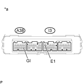
Text in Illustration *a Component without harness connected
(Power Management Control ECU)
Measure the resistance according to the value(s) in the table below.
Standard Resistance Tester Connection Switch Condition Specified Condition A38-19 (GI) - I3-6 (E1) Power switch off 10 kΩ or higher -
Connect the power management control ECU connectors.
NG
REPLACE POWER MANAGEMENT CONTROL ECU Click here
OK
-
-
CHECK INVERTER WITH CONVERTER ASSEMBLY
CAUTION:
Be sure to wear insulated gloves.
-
Check that the service plug grip is not installed.
Note
After removing the service plug grip, do not turn the power switch on (READY), unless instructed by the repair manual because this may cause a malfunction.
-
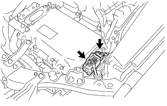
Disconnect the A14 inverter with converter assembly connector.
-
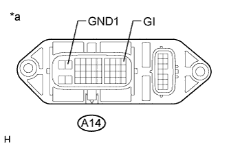
Text in Illustration *a Component without harness connected
(Inverter with Converter Assembly)
Measure the resistance according to the value(s) in the table below.
Standard Resistance Tester Connection Switch Condition Specified Condition A14-1 (GI) - A14-10 (GND1) Power switch off 10 kΩ or higher -
Reconnect the A14 inverter with converter assembly connector.
NG
REPLACE INVERTER WITH CONVERTER ASSEMBLY Click here
OK
REPLACE ECM Click here
-