REAR BUMPER REASSEMBLY

-
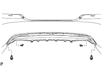
INSTALL REAR BUMPER REINFORCEMENT SUB-ASSEMBLY
-
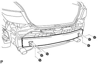
Install the rear bumper reinforcement sub-assembly with the 6 nuts.
- Torque:
- 61 N*m { 622 kgf*cm, 45 ft.*lbf }
-
-
INSTALL REAR BUMPER ENERGY ABSORBER
-
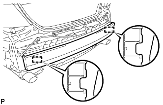
Engage the 2 guides to install the rear bumper energy absorber.
-
-
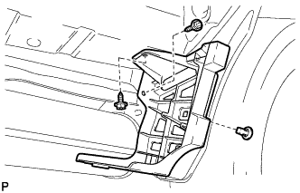
INSTALL REAR BUMPER SIDE SEAL LH
-
Engage the guide and claw.
-
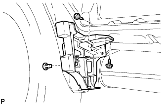
Install the 2 screws.
-
Install the rear bumper side seal LH with a new grommet.
-
-
INSTALL REAR BUMPER SIDE SEAL RH
-
Engage the guide and claw.
-
Install the 2 screws.
-
Install the rear bumper side seal RH with a new grommet.
-
-
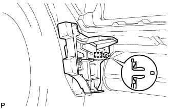
INSTALL REAR BUMPER SIDE RETAINER LH
-
Engage the 3 claws.
-
Engage the 3 clips to install the rear bumper side retainer LH as shown in the illustration.
-
-
INSTALL REAR BUMPER SIDE RETAINER RH
Tech Tips
Use the same procedure as for the LH side.
-
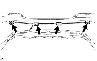
INSTALL REAR BUMPER LOWER COVER
-
Engage the 2 guides and 10 claws.
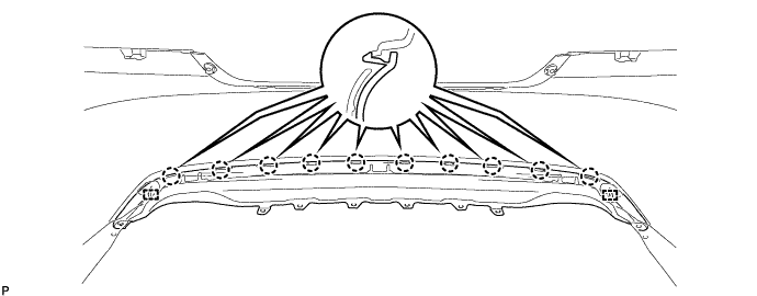
-
Install the 2 clips.
-
Install the rear bumper lower cover with the 2 outside moulding retainers.
-
-
INSTALL NO. 2 ULTRASONIC SENSOR RETAINER (w/ Intuitive Parking Assist System)
Tech Tips
Use the same procedure for all No. 2 ultrasonic sensor retainers.
-
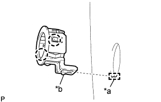
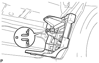
Text in Illustration *a Cutout *b Protrusion Engage the 2 claws to install the No. 2 ultrasonic sensor retainer to the rear bumper assembly.
Note
-
Do not damage the rear bumper assembly with the protrusion when installing the No. 2 ultrasonic sensor retainer.
-
Securely install the No. 2 ultrasonic sensor retainer so that there are no gaps between the No. 2 ultrasonic sensor retainer and surface of the rear bumper assembly.
Tech Tips
-
When installing the retainer, align the cutout and protrusion as shown in the illustration.
-
This illustration is for the LH side. The orientation for the RH side is the opposite of the LH side.
-
-
-
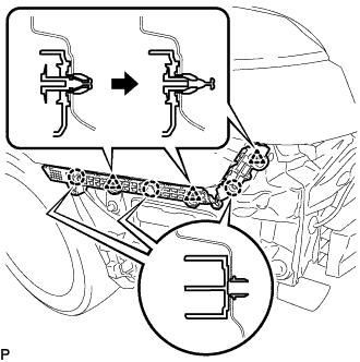
INSTALL NO. 1 ULTRASONIC SENSOR (w/ Intuitive Parking Assist System)
Tech Tips
Use the same procedure for all No. 1 ultrasonic sensors.
-
Engage the 2 claws to install the No. 1 ultrasonic sensor to the No. 2 ultrasonic sensor retainer.
Note
Push the No. 2 ultrasonic sensor retainer from the outside of the rear bumper assembly when there is a gap between the No. 2 ultrasonic sensor retainer and the rear bumper assembly surface. In this case, do not push on the No. 1 ultrasonic sensor.
-
-
INSTALL ULTRASONIC SENSOR CLIP (w/ Intuitive Parking Assist System)
Tech Tips
Use the same procedure for all ultrasonic sensor clips.
-
Engage the 4 claws to install the ultrasonic sensor clip.
-
-
INSTALL NO. 2 LUGGAGE ROOM WIRE (w/ Intuitive Parking Assist System)
-
Connect the 4 connectors.
-
Engage the 4 clamps to install the No. 2 luggage room wire.
-